Keep Earth Lead <0.5 m, Instrumentation Protection for Engineers
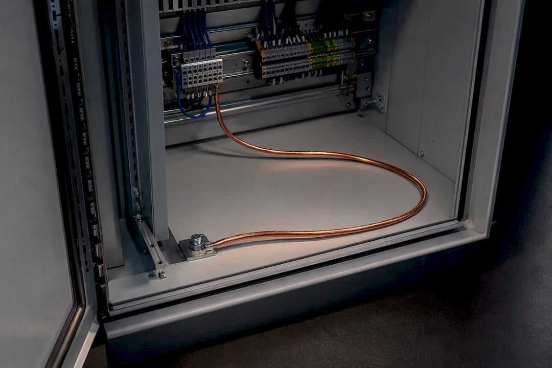
Protect instrumentation lines by pairing purpose-built signal SPDs or certified isolation/Zener barriers with short equipotential earth connections, installed at both the field entry and the control side. Match the device class to the loop type (4–20 mA, 0–10 V, or binary) and check clamp voltage and earth lead length before anything else. These practices follow IEC/EN 61643 for surge devices and IEC 61508/61511 where the loop feeds a safety function, reflecting standard field methodologies for industrial sites.
TL;DR:
- Proper grounding with short earth leads and bonding to the same earth reference is critical, as poor grounding is a leading cause of SPD failure.
- Installing protection devices at both the cable entry point and near the instrument ensures surge energy is intercepted before reaching sensitive electronics.
- Use certified Zener barriers or isolators for intrinsically safe loops, and verify that all protection devices are correctly rated and documented for safety compliance.
- Regularly test and maintain surge protection modules, replacing them after significant discharge events and confirming that earth impedance remains within recommended limits.
- Device selection must match the specific signal type and voltage, and grounding design must be integrated with device specification to ensure effective protection.
Table of Contents
- What Devices Actually Protect Instrumentation Lines?
- Where Should You Install Line Protection Devices?
- Why Grounding Determines Whether Protection Works
- Can You Use Standard SPDs on Intrinsically Safe Loops?
- Selection and Installation Checklist for Instrumentation Loops
- How Often Should You Test and Maintain Surge Protection?
- How Indelec Supports Instrumentation Protection Projects
- Where Engineers Get Instrumentation Protection Wrong
- Get a Standards-Aligned Protection Assessment
- Standards and Manuals Worth Keeping on File
- Sources
What Devices Actually Protect Instrumentation Lines?
Various device classes cover instrumentation scenarios, and picking an inappropriate one is a common specification error.
- Plug-in DIN-rail SPDs. Built for 0(4)–20 mA, 0–10 V, and binary signals up to roughly 60 V, these modules are tested to IEC/EN 61643-21 and installed per the IEC/EN 61643-22 application guidance. Check the residual voltage and the In rating (8/20 µs discharge current) against the transmitter’s tolerance before you order.
- Galvanic isolators. These preserve signal integrity across grounded segments and break ground loops, but they add capacitance and leakage current that can distort fast analog transients on a 4–20 mA loop.
- Zener diode barriers. Mandatory wherever the circuit needs intrinsic safety in a hazardous area. They limit voltage and current to the field side by design, not just clamp a transient.
- Series filters and surge capacitors. Useful for radio-frequency noise suppression, but adding capacitance carelessly on an analog loop shifts the frequency response and can trip diagnostics on smart transmitters.
Where Should You Install Line Protection Devices?
Placement decides whether the protection actually intercepts the surge before it reaches sensitive circuitry, or arrives after the damage is done.
- Install at the marshalling rack or cable entry point. This catches conducted surge energy the moment cabling crosses from the field into the control building, which matters most on long cable runs exposed to lightning-induced transients.
- Add a second device close to the instrument itself. Induced surges and common-mode coupling can appear downstream of the first SPD, especially in remote I/O cabinets fed by long, unshielded runs.
- Keep the earth lead as short as physically possible. Every extra centimeter of earth conductor adds inductance that raises the let-through voltage during a fast transient.
- Bond the SPD to the same earthing network as the protected device. A separate or distant ground reference defeats the purpose of the SPD regardless of its rating.
For distributed instrumentation with remote I/O nodes, this typically means one SPD bank at the field junction box and a second layer at the control room termination, both riding the same local earth bar.
Why Grounding Determines Whether Protection Works
Equipotential bonding is the part of the installation that decides whether an SPD actually functions, and it is the part most often done poorly. The core principle: the SPD and the instrument it protects must share the shortest possible earth path, because voltage difference during a surge, not the surge current itself, is what damages sensitive electronics.
- Keep the earth connection under roughly 0.5 meters where feasible, per Citel’s B280/B480 installation guidance.
- Use a minimum earth conductor cross-section of approximately 4 mm², unless the manufacturer datasheet specifies otherwise.
- Bond cable shields at both ends only when the design calls for it, and treat glands as part of the bonding path, not just mechanical strain relief.
- Never let separated zones (field enclosure, marshalling rack, control room) sit on different earth references during a surge event.
Poor grounding remains a leading cause of SPD ineffectiveness in the field, often more consequential than the nominal rating difference between two competing SPD models.
Pro Tip:Measure continuity and impedance between the SPD earth terminal and the instrument chassis with a low-resistance ohmmeter during commissioning, not just at final acceptance. A loose lug that passes a visual check can still add enough impedance to defeat the protection during a real strike.

Can You Use Standard SPDs on Intrinsically Safe Loops?
No, not without certification. Intrinsically safe circuits and safety-instrumented functions impose constraints that standard surge protection does not automatically satisfy.
- Zener barriers or certified isolators are required for intrinsically safe circuits; a general-purpose SPD is unsuitable unless it carries explicit ATEX or IECEx certification for that duty.
- Configuration changes made after commissioning can invalidate the safety-instrumented system’s SIL certification, so any protection device swapped into a certified loop needs documented configuration management, not a quiet field substitution.
- Barrier connections carry precise Uo, Io, Ro, and Po limits, and installers must match these exactly to the sensor’s certified parameters rather than approximate them.
- Loop protection design in a SIS context should go through the functional safety engineer, with proof-test intervals referenced against IEC 61508/61511 rather than set informally.
Selection and Installation Checklist for Instrumentation Loops
Specifying protection correctly means working through signal compatibility and installation rigor together, not treating them as separate steps.
- Identify the exact signal type and nominal voltage (4–20 mA, 0–10 V, or binary up to 60 V).
- Choose an SPD or isolation device with a clamp voltage and continuous operating voltage that clear the loop’s normal range with margin.
- Verify the In rating (8/20 µs) against realistic surge exposure for the site’s lightning risk.
- Confirm residual voltage stays below the instrument’s rated withstand voltage.
- Check leakage current and added capacitance against the loop’s accuracy tolerance, particularly for 4–20 mA measurement.
- Confirm ATEX or SIL compatibility whenever the loop sits in a hazardous area or safety function.
Installation checklist:
- Shortest practical earth lead, ideally under 0.5 meters.
- Same-earth bonding between SPD and protected instrument, verified by continuity test.
- Spare module slots and clear labeling for fast replacement.
- Accessible status indicators so a blown module gets noticed before it fails silently.
- A documented replacement policy triggered after any known surge event.
Improper or inadequate grounding is consistently identified as a leading cause of SPD failure or ineffectiveness in field installations, which is why the checklist above puts earthing ahead of device selection rather than after it.
How Often Should You Test and Maintain Surge Protection?
Surge protection degrades with every discharge event, and instrumentation loops feeding safety functions carry additional testing obligations beyond a visual check.
- Inspect SPD status LEDs on a routine schedule; most modules signal degradation before they fail completely, and a dark or red indicator means immediate replacement, not a wait-and-see approach.
- Replace any module that has absorbed a large discharge event even if it still shows a healthy status. Internal degradation from a near-rated hit is not always visible.
- Distinguish partial from comprehensive proof tests. Proof-test intervals for safety instruments are derived from reliability calculations, not from a generic annual default.
- After any known surge event, run a functional check, confirm residual voltage is within spec, and document the finding before returning the loop to service.
Pro Tip:Keep a log of every SPD replacement tied to a specific event date. A pattern of repeat failures on the same circuit almost always points to a grounding defect upstream, not a weak device.
How Indelec Supports Instrumentation Protection Projects
Instrumentation protection only works when grounding design and device selection happen together, on the same site survey, not as two separate contracts.
- Founded in 1955, Indelec runs a dedicated R&D center and provides risk assessments, deep earth grounding drilling, installation supervision, and certification services for industrial sites.
- Grounding quality is critical to ensuring that an SPD’s rated clamp voltage is effective in practice, so earthing design should be integrated with device specification rather than treated separately.
- On site, this typically involves a survey of existing earth resistance, potential grounding upgrades if bonding requirements are not met, and documentation covering the installed protection scheme for later audits or reviews.
Where Engineers Get Instrumentation Protection Wrong
The recurring mistake is not device selection. It is the earth conductor left long because the cabinet layout made a short run inconvenient. That single shortcut quietly raises the let-through voltage on every SPD downstream of it, and it rarely gets caught until a strike proves the point the hard way. The second most common mistake is applying a general-purpose SPD to a loop that is actually intrinsically safe, usually because the barrier requirement was not obvious from the panel layout.
Priority order matters here: fix grounding and equipotential bonding first, because a perfect SPD on a bad earth reference is close to useless. Select the right device class second. Document and schedule proof-testing third, and never skip it just because the loop has run fine for years.
Bring in specialist grounding and risk-assessment support when the site has known high earth resistance, a mix of intrinsically safe and standard loops, or a safety-instrumented function tied to the instrumentation. Straightforward single-loop retrofits with good existing earthing are often manageable in-house with the checklist above.
— INDELEC
Get a Standards-Aligned Protection Assessment
If your site mixes long cable runs, marginal earth resistance, and instrumentation feeding a safety loop, a generic SPD catalog order will not tell you what you actually need. Indelec builds its protection schemes around the site’s real grounding conditions, rather than a rated clamp voltage on a datasheet, combining risk assessment, deep earth grounding drilling where resistance is too high, device selection, and installation supervision under one engineering review.

That means one point of contact instead of separate vendors for grounding, SPDs, and certification paperwork. Request a site survey through Indelec’s lightning protection services and get a standards-aligned quote that covers commissioning support and the documentation package your safety file will eventually need.
Standards and Manuals Worth Keeping on File

For exact device limits and procedural requirements, consult the IEC/EN 61643 surge protection standards for SPD testing and application, IEC 61508/61511 for safety-instrumented function requirements, and the manufacturer’s own installation manual for clamp voltage, earth conductor sizing, and barrier parameters. Datasheet specifics vary enough between vendors that generic guidance should never replace the actual manual for the device in front of you.