4 Datasheet Checks Installers Must Do for Type 3 Surge Protectors
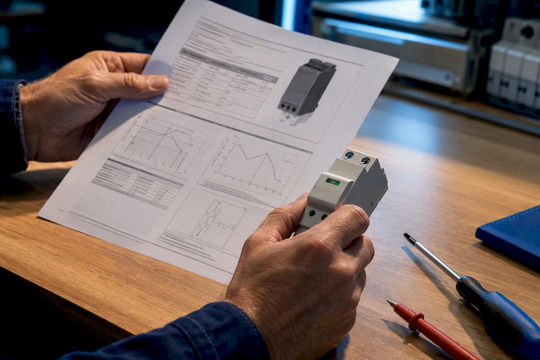
A Type 3 surge protective device is the point-of-use, final-stage SPD that clamps residual overvoltage at the equipment terminal. It always works alongside upstream protection, never instead of it. Install one when you’re feeding sensitive electronics, running long cable distances from the distribution board, or protecting a load where failure carries a real cost. On its own, a parafoudre type 3 handles only the leftover surge energy that Type 1 and Type 2 devices didn’t catch.
TL;DR:
- Install a Type 3 SPD only after confirming upstream protection stages are correctly specified and that the device’s Up voltage matches the system’s maximum overvoltage conditions.
- Keep wiring as short and direct as possible, and ensure proper bonding to low-impedance earth to prevent inductance or high-impedance paths from defeating the device’s effectiveness.
- Regularly inspect and test indicators or alarm contacts every quarter, and replace the device immediately after any high-energy surge or if indicators show degradation.
- Environmental factors such as high temperature, humidity, and pollution will accelerate SPD degradation, requiring tighter inspection intervals and appropriate enclosures based on site conditions.
- Coordination with Type 1 and Type 2 devices is essential, with a typical recommended separation of around 10 meters to prevent overstressing the Type 3 SPD and ensure system reliability.
Table of Contents
- What a Type 3 SPD Is: Function, Components, and Typical Formats
- When and Where Should You Install a Type 3 SPD?
- What Technical Parameters Should You Check Before Buying?
- Installation Best Practices and Wiring Details
- How Does Type 3 Coordinate With Type 1 and Type 2 Protection?
- Which Standards and Certifications Should You Verify?
- Maintenance and Inspection Routines That Keep Type 3 SPDs Working
- What’s the Typical Lifespan of a Type 3 SPD, and When Should You Replace It?
- How Do Temperature, Humidity, and Pollution Affect Type 3 SPD Performance?
- Indelec’s Perspective and Practical Recommendations
- Get Professional Specification and Installation Support
- Sources
What a Type 3 SPD Is: Function, Components, and Typical Formats
A Type 3 SPD sits at the very end of the surge protection chain, right where the wiring meets the equipment it’s guarding. Its job is narrow but critical: clamp any voltage spike that slipped past the upstream devices and divert that residual energy to earth before it reaches sensitive circuitry.
Three component types do the clamping, each with different reaction speeds. Metal oxide varistors (MOVs) absorb energy but respond a bit slower. Gas discharge tubes (GDTs) handle higher currents but ignite with a delay. Transient voltage suppression (TVS) diodes react in nanoseconds, which is why many Type 3 units combine a TVS stage with an MOV for both speed and capacity.
You’ll find Type 3 devices in a few practical formats:
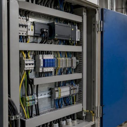
- DIN-rail modules mounted inside machine or control cabinets, wired directly into the local distribution circuit
- Plug-in or receptacle-style surge protectors for wall outlets feeding IT equipment or lab instruments
- Integrated modules built into sensitive appliances or panel assemblies
Under IEC 61643-11, these products carry a Class III rating, and that classification exists precisely because a parafoudre type 3 is designed for point-of-use, not for absorbing a direct or nearby lightning strike. The number to check first on any datasheet is Up, the voltage protection level. Lower is better for sensitive electronics.
When and Where Should You Install a Type 3 SPD?
A Type 3 belongs wherever the consequences of a voltage spike outweigh the cost of the device. That’s the whole decision rule, and it plays out in a handful of recurring scenarios.
- Server racks and data closets. Long cable runs from the main panel plus expensive, sensitive hardware make this the classic case for point-of-use protection.
- PLC cabinets and industrial control panels. A single corrupted signal or fried input card can shut down a production line for hours.
- Medical and laboratory equipment. Precision instruments often have tight tolerance for supply noise, and downtime has clinical consequences.
- EV charging points. Outdoor-facing charging infrastructure sits at the end of long feeder runs, exactly where residual transients reappear.
- Telecom and AV endpoints. Switches, matrix processors, and broadcast gear are frequently damaged by surges that a distribution board SPD never saw.
The trigger conditions are consistent across all five: distance from the main distribution board, equipment sensitivity, and the cost of failure. Placement follows the same logic. Mount the SPD inside the machine cabinet, at the wall outlet closest to the equipment, or directly at the device inlet. Protecting highly sensitive installations often means treating each critical load as its own protection zone rather than relying on a single upstream device for the whole building.
What Technical Parameters Should You Check Before Buying?
Datasheets for Type 3 devices pack a lot into a few rows, and misreading one field can leave equipment exposed even after installation. Four parameters matter more than the rest.
- Up (voltage protection level): this is the residual voltage let through during a surge. For protecting sensitive electronics, look for the lowest Up the application and budget allow.
- Uc (maximum continuous operating voltage): match this to your system voltage, typically 230V for single-phase circuits or 400V for three-phase, and confirm compatibility with your earthing scheme (TT, TN, or IT).
- Energy handling capacity: Class III devices are built for low-energy residual surges, not the high-current events that Type 1 or Type 2 devices absorb upstream.
- Disconnector and signalling options: check the manufacturer’s recommended fuse or disconnector rating, and whether remote alarm contacts are available for site monitoring.
Pro Tip:Don’t just match Uc to your nominal voltage. Check it against the highest sustained voltage your supply can realistically produce, including temporary overvoltage after a fault, or the SPD can degrade prematurely.
A Type 3 SPD that can’t handle sustained overvoltage, only transient spikes, will fail quietly long before a visible fault appears. That’s the tradeoff for its compact size: Type 3 units are built to be small and fast, not to absorb heavy lightning current, which is exactly why they can never stand alone.
Installation Best Practices and Wiring Details
Getting the specification right means nothing if the wiring undoes it. Every centimeter of extra conductor between the SPD and the protected equipment adds inductance, and that inductance raises the residual voltage the equipment actually sees, sometimes enough to erase the benefit of an otherwise well-chosen device.
- Minimize lead length. Route the SPD connection as directly as possible between the supply and the protected load. Treat any run longer than absolutely necessary as a design flaw to fix.
- Avoid loops and excess tail. Coiled or looped conductors act like small inductors, amplifying the voltage spike instead of suppressing it.
- Bond to a low-impedance local earth. Verify earth resistance and bonding continuity before commissioning. A high-impedance earth path defeats the SPD regardless of its rating.
- Fit the correct disconnector or fuse. Follow the manufacturer’s specified rating exactly. An undersized fuse trips prematurely; an oversized one leaves a failed MOV live.
- Test alarm contacts where fitted. If the site uses building management or remote monitoring, confirm the signalling circuit actually reports before you leave the panel closed.
Choosing between a plug-in receptacle SPD and a hardwired DIN-rail module comes down to accessibility. Plug-in units are easier to inspect and swap during routine maintenance rounds. DIN-rail modules integrate cleanly into cabinets and panels but need a planned shutdown for replacement. For complete facility installation, that maintainability tradeoff is worth mapping out before you commit to a format across an entire site.
How Does Type 3 Coordinate With Type 1 and Type 2 Protection?
A Type 3 SPD is never the whole solution. It’s designed to supplement Type 2 protection, and where a building faces direct lightning risk, Type 1 protection at the service entrance as well.
The cascade exists because energy has to be shared across stages. A Type 1 device at the main incomer handles the brute-force lightning current. Type 2 at the distribution board knocks the remaining surge down further. Type 3 finishes the job at the equipment terminal, clamping whatever residual voltage survived the first two stages.
- Coordination between stages depends on cable inductance between them, which is why field guidance commonly references a practical separation of around 10 meters between SPD stages where feasible.
- Skip the upstream device, or space the stages too closely, and the Type 3 can absorb energy it was never rated to handle, leading to overstress and premature failure.
- Plan cascaded protection at the design stage rather than retrofitting: map which distribution boards feed which sensitive loads before selecting devices for industrial surge solutions.
Missing or misplaced upstream protection is the single most common reason a correctly specified Type 3 fails within its first year.
Which Standards and Certifications Should You Verify?
Two IEC documents govern almost everything you need to check before procurement. IEC 61643-11 sets the classification system, Class I, II, and III, that determines a device’s test waveform and where it belongs in the cascade. IEC 61643-12 covers selection and application principles for coordinating multiple SPD stages.
For UK-based risk assessment methodology, IET guidance under BS 7671 ties the decision to install an SPD to the consequences of a surge event, not just its likelihood. That risk-based approach is a useful model for any site assessment, even outside UK jurisdiction.
Before purchase, confirm:
- CE marking and any third-party test certification (TUV, ECM, or equivalent) on the actual datasheet, not just marketing material
- The published Up value against the test waveform it was measured under
- Compliance references to IEC 61643-11 Class III specifically, not a vague “surge protected” claim
Maintenance and Inspection Routines That Keep Type 3 SPDs Working
An MOV degrades every time it clamps a surge, and that degradation is invisible without inspection. A device can look intact while its protection level has quietly crept upward, leaving equipment exposed during the next event.
Visual status indicators, most Type 3 units include a green/red window or LED, should be checked on a fixed schedule rather than only after a suspected surge event. Facility managers running critical loads typically fold this into quarterly electrical inspections alongside insulation resistance testing and earth continuity checks.

Where the SPD includes remote signalling or dry contacts, confirm the alarm circuit reports correctly to the building management system during each inspection. A silent failure, where the MOV has degraded but the indicator hasn’t tripped and the alarm contact wasn’t wired correctly, defeats the entire point of having remote monitoring in the first place.
After any known high-energy event, a lightning strike within the vicinity, a documented grid disturbance, or a utility switching event, inspect affected SPDs immediately rather than waiting for the scheduled cycle. Document each inspection with a date, indicator status, and earth resistance reading. That record matters twice: once for maintenance planning, and again if an equipment failure claim ever needs to demonstrate the protection system was properly maintained.
Replace on indication, not on a guess. A tripped indicator means the device has reached end of life for its protective components, even if it’s still passing current. Running a degraded SPD is functionally the same as running none at all.
What’s the Typical Lifespan of a Type 3 SPD, and When Should You Replace It?
Most Type 3 SPDs are rated for a service life in the range manufacturers publish per product, but real-world lifespan depends far more on surge frequency than on the calendar. A unit installed in a region with frequent grid disturbances or nearby lightning activity will absorb more clamping events, and each one degrades the MOV a little further.
Watch for these replacement indicators rather than relying on age alone:
- The status window or LED shows red, amber, or any non-green state specified by the manufacturer
- The device has absorbed a known high-energy event, even if the indicator hasn’t yet changed
- Visible discoloration, bulging, or a burnt smell near the SPD housing
- Nuisance tripping of the associated disconnector or fuse, which often signals a partially failed varistor drawing excess leakage current
A parafoudre type 3 that has silently failed open still allows current to flow normally, so equipment keeps running with zero protection until the next surge exposes the gap. That’s the operational risk with age-based assumptions: a five-year-old device in a low-surge environment might be fine, while a two-year-old device near industrial switching loads might already be spent. Facility teams managing multiple SPDs across a site benefit from tracking install dates and inspection results per device rather than assuming a uniform replacement cycle.
How Do Temperature, Humidity, and Pollution Affect Type 3 SPD Performance?
Environmental exposure shortens SPD service life faster than surge activity alone in many installations. Heat is the biggest factor: MOVs generate internal heat every time they clamp, and ambient temperatures above a device’s rated range accelerate the chemical degradation of the varistor material, shrinking both its lifespan and its effective protection level over time.
Humidity introduces a different failure path. Moisture ingress into cabinet-mounted or outdoor-adjacent SPDs can corrode terminal connections, raising contact resistance exactly where a low-impedance path matters most. For EV charging points and other outdoor-facing installations, an enclosure rating appropriate to the exposure isn’t optional. It’s part of the specification.
Airborne pollution, particularly in industrial environments with conductive dust or corrosive vapors, contaminates PCB surfaces and terminal contacts inside DIN-rail modules. That contamination can create leakage paths that either degrade clamping performance or, in worse cases, cause nuisance failures that trip protective disconnectors without any actual surge event.
The practical response is straightforward: match the SPD’s IP rating and operating temperature range to the actual site conditions, not the conditions in a generic datasheet example. A cabinet in a non-climate-controlled industrial hall faces a very different environment than a server room, even though both might specify the same electrical parameters. Where extreme conditions are unavoidable, tighter inspection intervals catch environmental degradation before it becomes an equipment failure.
Indelec’s Perspective and Practical Recommendations
Most installation problems with Type 3 devices don’t come from picking the wrong product. They come from skipping the paperwork that should happen before the product gets ordered. A one-page specification checklist, filled in during the site visit, solves most of it: document site exposure and surge history, confirm what upstream Type 1 or Type 2 devices already exist, set a target Up based on the sensitivity of the load, verify earth resistance, and measure the actual local lead length you’ll be working with.
Some companies have spent decades specifying protection systems for industrial and infrastructure clients where the cost of getting a cascade wrong isn’t theoretical, making industrial roof compliance in BC a critical aspect of safety and risk management. A parafoudre type 3 is a small, inexpensive part of that cascade, but it’s also the part most often installed without checking what’s upstream of it.
Our recommendation is consistent: run a proper site risk assessment before specifying anything, and have the installation verified by someone qualified to check earthing and coordination, not just wire it in and move on.
— INDELEC
Get Professional Specification and Installation Support
Reading a datasheet correctly is one thing. Getting the cascade, earthing, and lead lengths right on a live industrial site is another, and it’s where most Type 3 installations actually go wrong. Specialized providers work with facility owners, contractors, and engineering consultancies to specify and install complete surge and lightning protection systems, not just isolated components dropped into an existing panel.

If your site has sensitive electronics, long cable runs, or equipment where downtime is expensive, a proper risk assessment, installation, and maintenance program closes the gaps that a standalone Type 3 purchase can’t. Professional teams handle everything from the initial site audit through commissioning and ongoing inspection, so the coordination between Type 1, Type 2, and Type 3 stages is verified, not assumed. For facilities managing EV charging infrastructure or precision equipment, that same audit-first approach extends to charging station installation as well.
Contact a qualified provider to schedule a site risk assessment and get a specification built around your actual exposure, not a generic template.
Sources
Consult IEC 61643-11 classification guidance, NEMA’s SPD overview, and the Type 1/2/3 selection guide for standards background. Always verify final specifications against the manufacturer’s own datasheet and installation manual.
- Surge Protective Devices (SPD) – Protect home & electronics from power surges
- Guide de choix d’un parafoudre Type 1, Type 2, Type 3 — LPS Manager