What Is Structural Bonding in Lightning Protection?
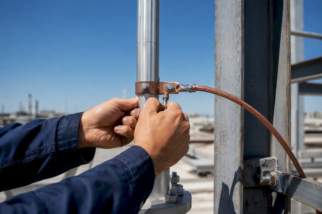
Structural bonding is the electrical interconnection of a building’s metallic parts (steel framing, pipework, cable trays, ductwork) to the lightning protection system and the common earthing network, so a lightning strike can’t create dangerous voltage differences between them. Without it, current looking for the shortest path to ground can jump between metal parts inside the building, and that jump is called a side-flash.
A few things to know before you go further:
- Get the right people involved. A lightning protection designer specifies bonding points, not the electrical contractor and not the site team improvising as they go.
- Check one thing today: is your lightning protection system actually tied into the Main Earthing Terminal? If nobody can answer that with certainty, you have a gap.
- The core safety fact:structural bonding exists specifically to eliminate dangerous potential differences and stop internal arcing between conductive building elements during a strike. IEC 62305 (published in Europe as EN 62305) is the standard that governs how this gets designed and verified.
Key Takeaways
Structural bonding works by equalizing electrical potential between a building’s metallic systems and its lightning protection network, and IEC/EN 62305 governs how that gets designed, sized, and verified.
| Point | Details |
|---|---|
| Definition | Structural bonding interconnects metallic building parts to the LPS and MET to prevent side-flashes and internal arcing. |
| Designer owns bonding decisions | Contractors should never finalize bond locations without documented approval from the LPS designer. |
| Plan bonding before the foundation pour | Fixed grounding lugs and inspection points need to go in while the foundation is still accessible. |
| Verify, don’t duplicate | Test for inherent bonding before adding new connections to avoid unnecessary cost and complexity. |
| Testing proves compliance | Continuity testing, disconnectable test joints, and documented records are what confirm the system still works. |
| Indelec’s role | Indelec designs, installs, and certifies structural bonding as part of full lightning protection projects, including site survey and deep earth grounding. |
Table of Contents
- Why Structural Bonding Matters for Life Safety and Fire Prevention
- How Does Structural Bonding Work With Air Terminals and Downleads?
- Which Standards Govern Structural Bonding Design?
- What Are the Best Practices for Bonding Design and Materials?
- How Do You Test and Verify Bonding Continuity?
- What Are Common Structural Bonding Mistakes to Avoid?
- Why Early Coordination Beats Retrofitting Every Time
- Get a Structural Bonding Design and Verification Review From Indelec
- Frequently Asked Questions
- Sources
Why Structural Bonding Matters for Life Safety and Fire Prevention
Bonding equalizes potential between conductive parts during a lightning event, and that single mechanism is what prevents side-flashes and internal arcing. When two nearby metal objects, say a downlead and a gas pipe, sit at different electrical potentials during a strike, the voltage difference between them can be enormous. Current will jump the gap rather than follow the conductor, and that arc can ignite gas, damage equipment, or injure anyone standing between the two objects.
The Lightning Protection Institute frames a complete system as strike termination, conductors, an earth termination network, bonding between the LPS and internal grounded systems, and surge protection at service entrances. Bonding isn’t an add on to that list. It’s the connective layer that makes everything else function as one system instead of five disconnected parts.
What happens when bonding is missing or done poorly:
- Touch and step voltages rise to levels that can injure people near grounded equipment.
- Internal arcing damages sensitive electronics, control panels, and wiring insulation.
- Fire risk increases sharply near gas lines, fuel storage, or flammable dust environments.
- Business continuity suffers when arcing takes out plant equipment mid-operation.
Picture a rooftop downlead running past a metal HVAC duct with no bonding jumper between them. During a strike, that gap becomes the arc path. Bond the two together at that point, and the arc path disappears.
How Does Structural Bonding Work With Air Terminals and Downleads?
Bonding is the interconnection step, not a standalone protective device. It doesn’t stop lightning and it doesn’t carry the main strike current on its own. Its job is to make sure every conductive object near the lightning protection system sits at the same electrical potential when current is flowing, so nothing “reaches” for a different path.
The components that need to work together:
- Air termination system, the rods, mesh, or conductors that intercept the strike.
- Downleads, which carry current from the air terminals to ground.
- Bonding conductors, which tie other metallic systems into that same electrical reference.
- Earthing and electrode system, the below-grade network that dissipates the current.
- Surge protection devices on power, data, and telecom lines entering the building, since bonding alone doesn’t protect conductors that continue beyond the building envelope.
Recommended bonding points typically sit near the base of each downlead, at the Main Earthing Terminal, at major metallic service entries (water, gas, telecom), and at intermediate floor levels in taller buildings. Comparative research on structural bonding methods, where the building’s own steel frame is used as part of the earthing path, has found this approach can produce lower earth electrode resistance than conventional external conductor systems, and it tends to be less vulnerable to theft or corrosion since the conductor is embedded in the structure rather than exposed on the exterior, which may reduce maintenance concerns.
Pro Tip:Always design at least two independent downlead paths with multiple bonding connections. Splitting the lightning current across parallel paths reduces the potential difference inside the building, which is exactly what side-flash prevention depends on.
Which Standards Govern Structural Bonding Design?
IEC 62305 (EN 62305 in the European context) requires the lightning protection system to be integrated with the building’s earthing and common Main Earthing Terminal, and it specifies the equipotential bonding measures needed to achieve that. This isn’t a suggestion buried in an appendix. It’s the framework a compliant design has to follow.
The standards landscape worth knowing:
- IEC/EN 62305 covers protection against lightning as a whole, including bonding arrangements.
- IEC 61643 family covers surge protective devices, which work alongside bonding at service entrances.
- BS 7671 (in jurisdictions that follow it) governs main protective bonding conductors for extraneous conductive parts, and explicitly requires that any connection between an LPS and protective equipotential bonding follow BS EN 62305.
The lightning protection system designer, not the electrical contractor and not whoever is on site that day, is responsible for specifying bonding locations, conductor sizes, and testing points. Contractors should never finalize bond positions without documented designer approval, since ad hoc bonding decisions can introduce unintended parallel paths for lightning current instead of eliminating them.
What Are the Best Practices for Bonding Design and Materials?
The basic design rule: bond at grade to the Main Earthing Terminal, bond at roof and intermediate levels in taller buildings, and size every bonding conductor according to the standard rather than whatever cable happens to be in the truck. In multi-story buildings, bonding at multiple levels matters because long vertical conductor runs generate real potential differences that can cause internal arcing if left unequalized between floors.
Typical bonding locations a specification should call out:
- Downlead bases and the Main Earthing Terminal
- Water and gas pipe entries, on the customer side of the meter
- Communication and data cable sheaths
- Structural steel framing, where continuity and cross section meet the standard’s criteria
- Roof drains, ladders, HVAC casings, and cable trays
On materials, use conductors sized to the applicable standard’s minimum cross section for the metal in question, and match materials to avoid galvanic corrosion where copper meets steel or aluminum. Mechanical durability matters as much as conductivity: a bonding connection that corrodes or loosens within five years is a compliance failure waiting to surface during the next inspection.
Pro Tip:Coordinate with the foundation contractor before the pour. Fixed grounding lugs and inspection points need to go into the foundation while it’s still accessible. Retrofitting bonding into a finished structure is one of the most expensive corrections in this entire field, and it’savoidable with early planning.

How Do You Test and Verify Bonding Continuity?
Continuity testing and documented test joints are what prove a bonding network still works, and “it looked fine during installation” doesn’t count as verification five years later. Disconnectable test joints at grade allow earth resistance measurements without permanently disrupting the bonding network, which is why they belong in the design from day one, not added afterward.
A working verification checklist:
- Visual inspection of all accessible bonding connections and conductors.
- Continuity testing using the long-lead method between bonded points.
- Earth resistance checks at test joints where applicable.
- Confirmation that disconnectable joints remain accessible for future measurement.
- Photographic records of each connection before it’s concealed.
Keep as-built drawings showing every bonding point, test certificates from each inspection cycle, and a maintenance log that tracks when the system was last checked. Facility teams that skip this documentation usually find out the hard way, during an insurance claim or a post-incident investigation, that they can’t prove the system was ever compliant.
What Are Common Structural Bonding Mistakes to Avoid?
Myth: a foundation ground rod alone is sufficient.
Fact: a single rod is often insufficient without multiple fixed grounding points and proper interconnection across the structure. One rod gives you a resistance value, not a bonded network.
Myth: every metallic part in the building needs a brand new bond.
Fact: many components are already inherently bonded through welds, continuous piping, or connection to water mains. Verify inherent bonding with inspection or resistance testing before adding redundant connections that add cost without adding safety.
A short procurement checklist worth pinning to the wall:
- Appoint a qualified lightning protection designer before foundation work starts.
- Put bonding details on the structural and foundation drawings, not a separate document nobody reads on site.
- Locate fixed grounding lugs before the concrete pour.
- Verify inherent bonds with testing rather than assuming.
- Record every testable disconnect point on the as-built drawings.
- Schedule periodic continuity checks as part of routine maintenance.
Why Early Coordination Beats Retrofitting Every Time
Design responsibility isn’t a formality. It’s the difference between a bonding system that gets designed once, correctly, and one that gets patched together after someone notices a gap during a routine inspection. Early coordination between the lightning protection designer, structural engineer, and electrical contractor costs far less than opening up finished walls or foundations to add a bonding lug that should have gone in during the pour.
We’d rather see a facility manager ask too many questions during design review than sign off on a system nobody can verify five years from now.
Pro Tip:Insist on a printed bonding layout as part of the record drawings, and make sure every bonding point on that layout is physically testable. A drawing that shows bonds nobody can access in the field is not documentation, it’s a liability.
Get a Structural Bonding Design and Verification Review From Indelec
Since 1955, Indelec has designed, installed, and certified lightning protection systems where structural bonding isn’t an afterthought bolted onto the project at the end. It’s part of the initial site survey, alongside earth resistance measurement, risk assessment, and coordination with the structural and electrical trades before foundations get poured.

Working with Indelec typically starts with a site survey to assess existing grounding, structural steel, and service entries, followed by a design that specifies bonding points, conductor sizing, and test joint locations per IEC/EN 62305. Installation and certification follow, including the continuity testing and documentation a facility manager needs on file. Indelec’s deep earth grounding drilling service supports low-impedance earth systems on sites where soil conditions make a straightforward ground rod insufficient.
If your project is still in design, or if an existing bonding system has never been formally verified, request a site survey and design review from Indelec before the next inspection cycle catches a gap you’d rather have found first.

Frequently Asked Questions
What is structural bonding in a lightning protection system?
Structural bonding is the electrical interconnection of a building’s metallic components, structural steel, pipework, cable trays, and ductwork, to the lightning protection system and common earthing network, done to eliminate dangerous potential differences and prevent side-flashes during a strike.
Is structural bonding the same as functional bonding?
No. Structural (equipotential) bonding addresses lightning-related potential differences across the entire building and its lightning protection system. Functional bonding is a narrower electrical engineering concept related to signal reference and equipment performance, and the two shouldn’t be conflated during design review.
Who decides where bonding connections go?
The lightning protection designer specifies bonding locations, conductor sizes, and test points based on IEC/EN 62305. Contractors implement that design; they shouldn’t be making bonding placement decisions independently on site.
Is structural bonding strong enough to prevent all lightning damage?
Bonding is one layer of a complete system that also includes air terminations, downleads, an earth electrode network, and surge protection devices. It’s highly effective at preventing side-flash and internal arcing specifically, but it doesn’t replace the other components.
How is structural bonding different from welding two metal parts?
Bonding is an electrical connection designed to equalize potential and carry fault or lightning current safely; welding is a mechanical joining method. A welded joint can serve as an inherent bond if it meets continuity and cross-section requirements, but not every weld qualifies without verification.
How often should bonding connections be tested?
Most facilities schedule continuity testing and visual inspection annually, with more frequent checks in corrosive or high-risk environments. Documentation from each test cycle should be kept alongside the as-built bonding drawings.
Sources
For readers who want the primary source material behind this article’s guidance:
- LPI-177 (Lightning Protection Institute guidance)
- Lightning protection and equipotential bonding (Hydrogroup product manual)