Ground Resistance Explained: How to Measure, Read, and Fix It
Ground resistance is the opposition, measured in ohms, that a grounding system presents to fault or lightning current trying to dissipate into the earth. The lower that number, the faster current disperses and the less dangerous voltage builds up on exposed metal during a fault. A useful reading tells a technician one thing above all: whether a grid will hold step and touch potentials to a survivable level and let protective relays clear a fault before equipment or people get hurt.
A few things worth knowing before you touch a meter:
- Low ground resistance limits step and touch potential hazards during a fault, which is the entire safety case for testing in the first place.
- Resistance and relay coordination are linked. A grid that clears faults too slowly lets current linger and voltage gradients spread.
- The measured number is method-dependent. Fall-of-potential, clamp-on, and selective testing can return different values on the same electrode.
- Soil moisture and temperature shift readings by season, so one test on one day is a snapshot, not a certification.
**Ground resistance testing across seasons or poor grounding maintenance is a recognized cause of downtime, equipment damage, and safety incidents, which periodic testing is specifically designed to catch before failure.
Key Takeaways
Ground resistance depends on soil resistivity, electrode geometry, and system bonding, and no single ohm value applies to every application without a fault-current and GPR calculation.
| Point | Details |
|---|---|
| Resistance versus resistivity | Ground resistance (Ω) depends on electrode design; soil resistivity (Ω·m) is an intrinsic soil property. |
| Depth beats diameter | Doubling rod length cuts resistance roughly 40%, while doubling diameter saves only about 10%. |
| Plateau checking is essential | Invalid fall-of-potential readings usually come from a potential probe placed too close to reach remote earth. |
| Targets vary by application | IEEE 80 ties acceptable resistance to available fault current and GPR, not a fixed universal number. |
| Professional remediation for hard cases | Indelec offers deep earth grounding drilling and acceptance testing for sites where surface fixes fall short. |
Table of Contents
- Ground Resistance Explained: How It Differs From Soil Resistivity
- What Actually Determines Ground Resistance?
- How Do You Measure Ground Resistance in the Field?
- What Ground Resistance Value Should You Target?
- How Do You Lower Ground Resistance?
- What Maintenance Habits Prevent Ground Resistance Failures?
- Worked Example: Calculating and Interpreting a Reading
- What Equipment Do You Need for Ground Resistance Testing?
- What Field Experience Teaches About Ground Resistance
- Professional Ground Resistance Testing and Remediation Services
- Sources
Ground Resistance Explained: How It Differs From Soil Resistivity
Engineers routinely conflate two numbers that measure different things. Ground resistance, in ohms, is the opposition an installed electrode or grid presents to current flowing into the surrounding earth. Soil resistivity, in ohm meters, is an intrinsic property of the ground itself. It tells you how hard the earth resists current flow independent of any electrode design.
The distinction matters because soil resistivity is a property of the site, while ground resistance is the outcome of that soil property combined with electrode length, depth, spacing, and material. You cannot change the resistivity of the dirt under a substation without physically treating it, but you can absolutely change the resistance of the grounding system installed in that dirt.
Two measurement geometries dominate the field. The Wenner four-pin method drives four equally spaced electrodes in a line, injects current through the outer pair, and reads voltage across the inner pair, producing an apparent resistivity value at a given probe spacing. Fall-of-potential testing works differently: current flows between the electrode under test and a remote current stake, while a potential probe placed between them samples voltage at increasing distances until the reading flattens into a plateau.
Which one you run depends on what phase of the project you’re in.
- Measure soil resistivity during design and modeling, before an electrode is ever installed, to size the grid and predict performance.
- Measure ground resistance during acceptance testing, after installation, and again periodically to confirm the system still performs and hasn’t degraded.
What Actually Determines Ground Resistance?
Three categories of variables drive every reading you’ll take in the field: the soil, the electrode, and the system it’s connected to.
Soil factors dominate. Resistivity depends on moisture content, temperature, and the concentration of dissolved salts and minerals in the ground. Layered soils, common where clay sits over rock or sand over gravel, complicate things further because current takes the path of least resistance through whichever layer conducts best. Moisture and temperature swings shift resistivity by season, sometimes dramatically, which is why a single measurement taken during a drought can mislead a design review.
Electrode factors are where engineers have real control. Depth and length matter more than almost anything else you can adjust: doubling a rod’s length can cut resistance by roughly 40%, while doubling its diameter buys you only a modest improvement. That asymmetry surprises a lot of people who assume a fatter rod is a better rod. Number of electrodes, spacing between them, and material choice (copper-clad steel versus solid copper versus galvanized steel) round out the list.
System factors cover everything downstream of the electrode itself: bonding quality, connection torque, corrosion at clamps and welds, and whether the grid has parallel paths through utility neutrals, cable sheaths, or building steel that quietly lower the apparent resistance during testing.
Here’s roughly what to expect by soil type, treated as a starting point for diagnosis rather than a guarantee:
| Soil Type | Typical Resistivity Range | Rough Earthing Resistance Guidance |
|---|---|---|
| Wet organic soil / marsh | 10 Ω·m | Can achieve under 5 Ω with a single rod in favorable spots |
| Moist clay | 100 Ω·m | Often 5–15 Ω with standard rod lengths |
| Sandy soil, moist | 200 Ω·m | Frequently 15 Ω without additional electrodes |
| Dry sandy or gravelly soil | 1,000 Ω·m | Often exceeds 40 Ω, mesh or multiple rods usually needed |
| Rock or frozen ground | 3,000 Ω·m | Chemical treatment or deep drilling typically required |

These figures come from Fluke’s grounding basics guidance and reflect wide real-world variation. Treat them as a sanity check, not a spec.
How Do You Measure Ground Resistance in the Field?
Four methods cover nearly every situation you’ll encounter, and picking the wrong one is the fastest way to get a number that looks fine on paper and fails during an actual fault.
Fall-of-potential (three-point) testing is the accepted method for acceptance testing an isolated grounding system.
- Disconnect the electrode or grid from any parallel ground path so you’re testing it in isolation.
- Drive a current stake far from the electrode under test, typically several times the maximum grid dimension.
- Insert a potential probe between the electrode and the current stake, starting close to the electrode.
- Take resistance readings as you move the potential probe outward in increments.
- Plot the readings and look for a plateau, the flat region where moving the probe barely changes the reading. That plateau is your valid result.
- As a starting rule of thumb, the 62% point between the electrode and current stake often lands in the plateau for a single isolated rod, though this shortcut gets unreliable fast on large grids.
For substations or large grids, the 62% rule can mislead you because current electrode spacing may need to run 5 to 10 times the grid diagonal to reach a genuine plateau. On constrained sites, angled traverses substitute for straight-line spacing when you can’t get that much clearance.
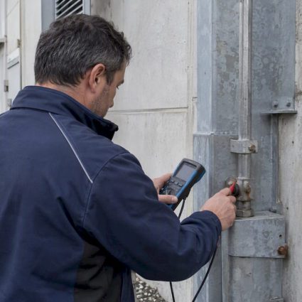
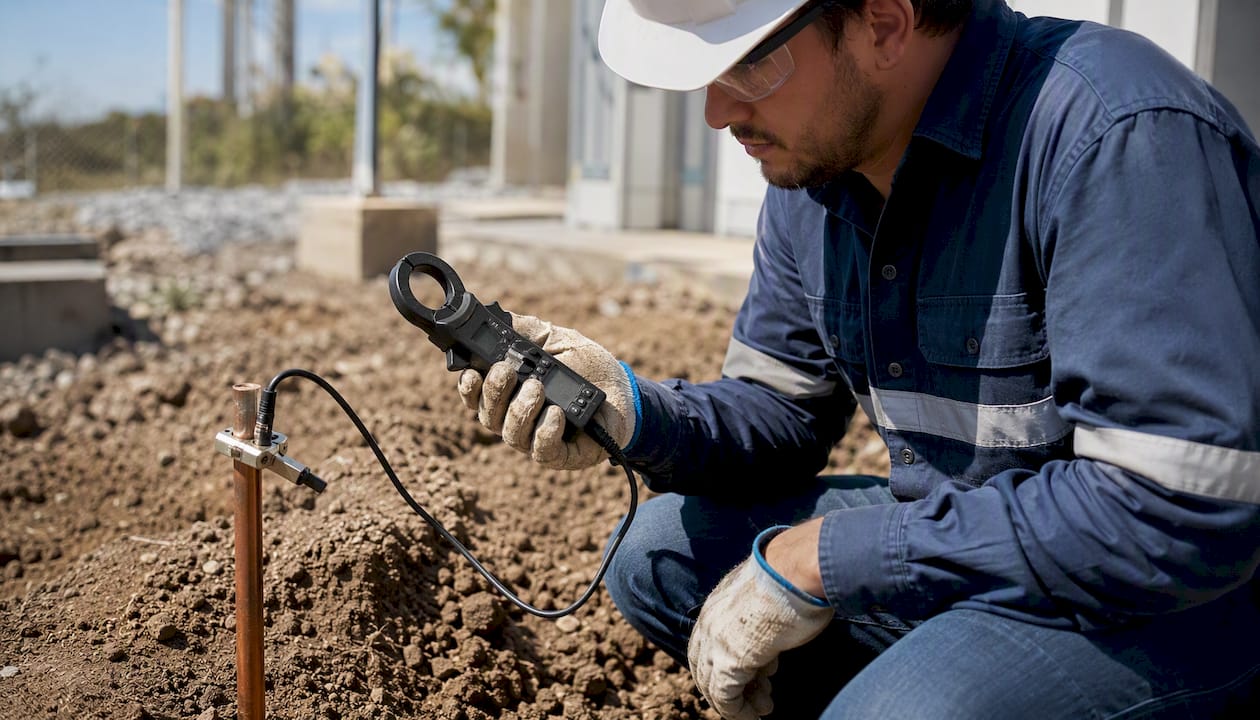
Stakeless (clamp-on) testing works by electromagnetic induction. You clamp around a single conductor and read resistance without disconnecting anything. It’s fast, safe, and ideal for in-service screening of individual rods or condition monitoring, but it measures the rod in series with every other parallel path back to the source. On sites with many bonded grounds, that parallel combination can be low enough that the clamp reading approximates the rod alone, which is useful for trending but not for certifying a whole grid at acceptance.

Selective testing solves the problem of multi-grounded systems you can’t disconnect, common on operating substations or distribution networks tied into utility neutrals. It combines a clamp-on current transformer with a fall-of-potential style voltage measurement to isolate the resistance of one electrode within a bonded system, without taking anything offline.
Wenner four-pin resistivity testing measures the soil itself, not an installed electrode, and belongs in the design phase or whenever you need resistivity input for a grid model.
Pros and cons in short: fall-of-potential is the gold standard for acceptance but needs land and isolation. Clamp-on is fast and safe but can’t replace acceptance testing on a full grid. Selective testing handles bonded systems but requires more equipment and setup. Wenner gives you design data, not a resistance value.
Pro Tip:Always confirm the plateau with at least three readings at different potential probe positions rather than trusting a single point. If the reading keeps drifting as you move the probe outward, you haven’t reached remote earth yet, and the number you’re about to write down is wrong.
Document soil conditions, probe spacing, ambient temperature, and the Wenner profile alongside every result. That record is what makes a retest three years later actually comparable to the acceptance test.
What Ground Resistance Value Should You Target?
There’s no universal ohm number that applies to every site, and anyone who tells you otherwise hasn’t read the standard. IEEE 80 ties acceptable resistance to available fault current and tolerable ground potential rise, not to a fixed target. IEC and EN standards, along with national wiring codes, work the same way: they set a design methodology, not a single magic number.
That said, industry practice clusters around some rough bands worth knowing as reference points:
- Large transmission substations often target a low resistance value, because available fault current is enormous and GPR limits are tight.
- Distribution substations commonly target a moderate resistance value, reflecting lower fault current but still meaningful risk.
- General commercial or industrial sites frequently accept a broader range, sometimes into double digits, depending on the specific equipment being protected and local code.
None of these numbers substitutes for a real calculation. Verify against the site’s actual available fault current, the applicable lightning and grounding standards for your jurisdiction, and the project specification before you sign off on any acceptance test. A grid that hits 3 Ω might be excellent for one application and dangerously inadequate for another.
How Do You Lower Ground Resistance?
When a measured reading comes back higher than the design target, you have several remediation paths, each with different cost and longevity trade-offs.
- Additional rods, spaced at least their own length apart to avoid overlapping resistance zones, add parallel paths and lower overall resistance incrementally.
- Deeper electrodes exploit the fact that depth reduces resistance far more efficiently than diameter, particularly useful where surface soil is dry or rocky but moisture improves with depth.
- Ground mesh or grid systems spread current over a larger area and are standard for substations where step and touch potential control matters as much as raw resistance.
- Chemical or graphite backfill surrounds the electrode with a conductive, moisture-retentive material that lowers the effective resistivity of the soil immediately around the rod. It works well in poor soils but the backfill has a service life and needs periodic inspection.
- Ground plates offer more surface area than a rod in shallow-soil sites where depth isn’t an option.
- Conductive grout or concrete suits retrofit situations where excavation is limited.
- Soil conditioning, adding moisture-retentive or conductive amendments, is a slower, more site-specific fix best reserved for chronic problem soils.
A rough decision path: if one or two rods miss target by a small margin, add rods first since it’s the cheapest fix. If soil resistivity is uniformly poor across a large area, a mesh or grid usually outperforms adding rods one at a time. If excavation or access is genuinely limited, chemical backfill or deep earth grounding drilling into lower-resistivity strata often beats surface-level fixes.
Chemical backfill and conductive grout both carry longevity caveats. Backfill can leach or dry out over years, and any conductive additive in contact with dissimilar metals raises corrosion questions worth checking against local soil chemistry, particularly near coastal or high-salinity ground where accelerated corrosion is already a known risk for buried metal. As a rough cost-to-effectiveness guide: additional rods are cheapest and easiest to justify; mesh systems cost more upfront but scale well for large sites; chemical treatment and deep drilling command a premium but solve problems that rods simply can’t in rock or high-resistivity ground.
What Maintenance Habits Prevent Ground Resistance Failures?
A grounding system that passed acceptance testing five years ago isn’t necessarily fine today. Corrosion at clamps, loosened connections, and drying soil all degrade performance quietly.
- Inspect visible connections annually for corrosion, loose torque, and physical damage.
- Run periodic clamp-on checks to establish a baseline and catch drift between full acceptance-style retests.
- Keep records of every test, including soil conditions and probe spacing, so trends are comparable over time.
The most common testing mistake is inadequate potential probe spacing on fall-of-potential tests, which returns a falsely low reading because the measurement never reaches remote earth. A close second is failing to isolate parallel ground paths, which similarly understates true resistance. And treating a single seasonal reading as a permanent verdict is a habit worth breaking, since a test run after a dry summer can look alarming compared to one run after a wet spring on the exact same electrode.
Retest after major construction near the grid, after a lightning strike, after a drought, and on a routine schedule otherwise, commonly annually for critical infrastructure and every few years for general commercial sites. One warning worth repeating: a low resistance reading alone does not confirm safe step and touch potentials. That requires a proper GPR analysis, not just an ohm number.
Worked Example: Calculating and Interpreting a Reading
Say you’re running a fall-of-potential test on a single ground rod. You apply a known test current and measure voltage at several probe positions, watching for the plateau.
- At the probe position that shows a stable plateau, you record a voltage of 4.2 volts with a test current of 2.0 amps.
- Resistance follows Ohm’s law applied to the ground test: R = V / I = 4.2 / 2.0 = 2.1 Ω.
- You confirm this is valid by checking two adjacent probe positions and seeing readings within a few percent, roughly 2.05 and 2.15 Ω, which confirms you’ve found the plateau rather than a transient slope.
Now suppose you also ran a Wenner resistivity test at 5 meter pin spacing and measured an apparent resistance of 15.9 Ω across the inner pins. The Wenner formula is:
ρ = 2πaR, where a is the pin spacing in meters and R is the measured resistance in ohms.
Plugging in: ρ = 2 × π × 5 × 15.9 ≈ 500 Ω·m. That figure becomes an input to a grid design model, not a direct comparison to your 2.1 Ω rod reading. They answer different questions.
If your design target for this application was 5 Ω, a measured 2.1 Ω passes comfortably. If the target had been 1 Ω, for a transmission-class installation, you’d be looking at additional rods, a deeper electrode, or a small mesh to close the gap before signing off.
What Equipment Do You Need for Ground Resistance Testing?
A handful of instrument types cover essentially every job. Earth ground testers capable of fall-of-potential are the core acceptance-testing tool. Clamp-on ground testers handle screening and in-service condition monitoring without disconnecting anything. Four-pin resistivity meters run Wenner tests for design work. Insulation testers, portable current sources, and a reliable voltmeter round out a field kit.
Fluke and Megger both make earth and ground resistance testers widely available and commonly specified on acceptance-test procedures. For short one-off jobs, renting a fall-of-potential tester often makes more financial sense than buying. For ongoing maintenance programs or utilities running acceptance tests regularly, owning a dedicated unit pays for itself quickly.
For substation-scale grids, remediation involving deep drilling, or certification work, qualified contractors bring calibrated equipment and the experience to interpret plateau data correctly. This isn’t a DIY category once the stakes involve large fault currents or public infrastructure.
What Field Experience Teaches About Ground Resistance
Grounding systems get designed on paper and then forgotten in the ground for decades. The gap between those two realities is where most of the real problems live. A grid modeled correctly with clean Wenner data can still fail an acceptance test years later because a connection corroded or the water table dropped, and nobody thinks to check until something goes wrong during a fault.
Indelec’s research and development work centers on exactly this gap between design assumptions and installed performance, including deep-drilling capability for reaching lower-resistivity strata in difficult soils where surface rods simply won’t hit target. Acceptance testing isn’t paperwork. It’s the only real evidence that a design survived contact with actual ground.

This guidance is technical and written for qualified personnel. Any modification to an existing grounding or lightning protection system should go through a professional with the equipment and training to do it safely.
Professional Ground Resistance Testing and Remediation Services
Indelec gives engineering teams a faster path from a failed acceptance test to a compliant grid, without the guesswork of trial-and-error rod additions on a site with poor soil.

Field testing tells you where a grid stands. Fixing it, especially in rock, dry soil, or coastal ground where corrosion accelerates, is a different skill set. Indelec’s services cover the full path from diagnosis to certification:
- Site assessment and soil resistivity profiling using Wenner and fall-of-potential methods.
- Deep earth grounding drilling for sites where surface electrodes can’t reach acceptable resistance.
- Acceptance testing, remediation design, and certification documentation.
Hire a contractor when the grid is large, access is limited, isolation for fall-of-potential testing is impractical, or the site feeds a substation or other critical infrastructure. Explore Indelec’s lightning protection system application page to see how grounding integrates into a complete protection design, and get in touch for a site assessment before your next scheduled retest comes due.
Sources
- Fluke — Earth ground testing resources and grounding basics
- Substation Ground Resistance Testing: Fall of Potential — Southern Switch
- AEMC ground testing workbook — Wenner and resistivity testing methods