What Is a Down Conductor in a Lightning Protection System?
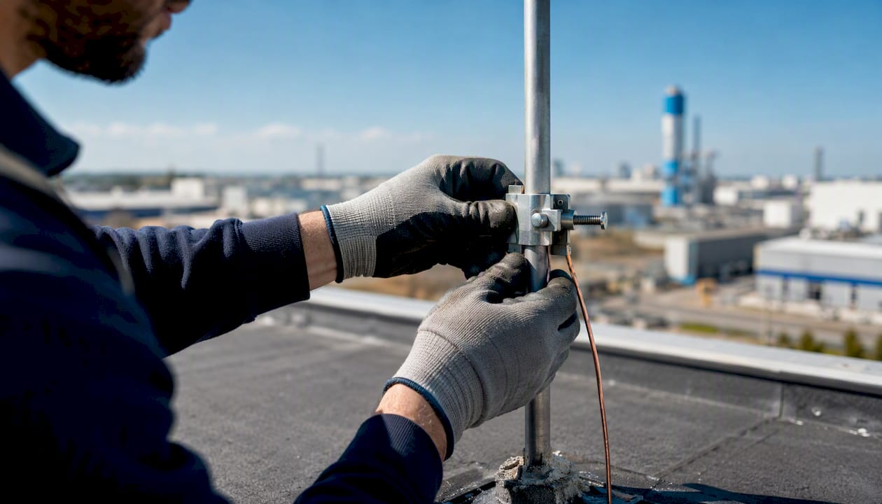
A down conductor is the metallic path that carries lightning current from the air-termination system, the rod or mesh that first intercepts a strike, down to the earth-termination system, where the energy dissipates into the ground. It is the middle link in a three-part chain, and if it fails, the other two links don’t matter.
A few facts every technician should have memorized before stepping onto a roof:
- Down conductors handle lightning currents up to about 200 kA during a direct strike, for a duration measured in microseconds.
- Copper and aluminum are the standard materials, with cross-sections typically running from 50 to 150 mm² depending on form and alloy.
- The governing references are the IEC/EN 62305 series internationally and NF C 17-102 for ESE-based systems in France.
- This matters most on tall structures, industrial plants, telecom masts, and any site with combustible roofing or stored materials nearby, where a poorly routed conductor turns a survivable strike into a fire.
Pro Tip:Never treat the down conductor as “just a wire.” Its geometry, not just its cross-section, determines how much of the strike energy stays where you want it and how much jumps sideways into something it shouldn’t touch.
Key Takeaways
A down conductor works by giving lightning current a low-inductance, continuous path to earth, and every routing or material shortcut that raises inductance or breaks continuity increases the risk of a side flash or fire.
| Point | Details |
|---|---|
| Core function | The down conductor carries lightning current from air termination to earth termination, handling pulses up to 200 kA. |
| Route straight and vertical | Avoid loops and sharp bends; keep bend radius near 20 cm (8 in) and angles under 45 degrees where possible. |
| Match material to environment | Use copper for coastal or buried applications; reserve aluminum for dry, non-masonry-contact runs. |
| Bond everything nearby | Bond all metallic services within the counterpoise radius to prevent dangerous potential differences. |
| Test before and after strikes | Confirm continuity and earth resistance at acceptance, then repeat inspection within 48 hours of any suspected strike. |
Table of Contents
- How Does a Down Conductor Work Inside an LPS?
- What Materials and Cross-Sections Do Down Conductors Use?
- Which Standards Govern Down Conductor Sizing and Design?
- How Should a Down Conductor Be Routed and Installed?
- How Does a Down Conductor Connect to the Earthing System?
- What Accessories and Connectors Does a Down Conductor Need?
- How Often Should Down Conductors Be Inspected and Tested?
- What Belongs in a Down Conductor Specification Checklist?
- An Engineer’s View on Down Conductor Tradeoffs
- Standards and Resources to Consult Before Specifying a System
- Frequently Asked Questions
- Sources
How Does a Down Conductor Work Inside an LPS?
A down conductor works by giving lightning current the path of least resistance to ground, so it never has a reason to jump through your building instead. Current strikes the air terminal, travels down the conductor, and disperses through the earth-termination system into the soil. That’s the whole job description, but the physics behind it is what separates a compliant installation from a liability.
The current pulse itself is brutal and brief. You’re looking at up to 200 kA rising and falling within microseconds, not the sustained current you’d see in a fault condition. This transient nature is exactly why impedance and continuity matter more than simple resistance. A conductor that measures fine on a slow ohmmeter test can still behave badly under a fast-rising pulse if its inductance is high, because inductive reactance scales with the rate of current change, not the DC resistance.
That’s the electrical reason installers insist on straight, vertical runs. Every bend adds inductance. Every loop adds more, and a loop under a fast transient can generate enough voltage to arc across the gap, known as a side flash, even when the conductor itself remains intact. Multiple parallel down conductors solve part of this problem by dividing the current: if a structure uses four down conductors instead of one, each carries roughly a quarter of the total pulse, which reduces both the thermal load and the magnetic field each individual conductor generates.
Picture the current at the top of the structure splitting at each parallel down conductor, each path carrying a fraction of the total pulse toward its own earth connection. Fewer amps per path means less magnetic coupling with everything running alongside it, including data cables, gas lines, and structural steel.
That splitting behavior is also why spacing between parallel conductors isn’t arbitrary. Too close together and they behave electromagnetically like a single conductor, defeating the purpose of splitting the current in the first place.
What Materials and Cross-Sections Do Down Conductors Use?
Down conductors come in a handful of practical forms, and the right one depends on the structure, the budget, and how much of the run will be exposed versus buried. Solid round conductors remain the standard for straightforward roof-to-ground runs. Stranded or braided cable flexes better around irregular geometry and is common on masts and towers. Flat tape conductors save space on parapets and cornices where a round profile would be awkward to clamp. Insulated or over-sheathed conductors show up in isolated LPS designs where separation distance from occupied areas is a design requirement rather than a nice-to-have.
Structural steel deserves a mention here too. Many buildings can use their own reinforcing steel or structural frame as a natural down conductor, provided electrical continuity is verified and documented, which saves material cost but demands rigorous testing during construction.
Copper and aluminum remain the two workhorse materials, and each comes with tradeoffs worth knowing before you spec a job.
| Material | Typical cross-section range | Conductivity | Notes |
|---|---|---|---|
| Copper (solid or stranded) | 50–150 mm² | High (typical for copper) conductivity | Best corrosion resistance; standard for coastal and industrial sites |
| Aluminum | 70–150 mm² | Lower conductivity, needs larger cross-section for equivalent capacity | Lighter, cheaper, but not suitable for direct burial or contact with masonry without protection |
| Tinned copper tape | 50–150 mm² | High, with added surface protection | Preferred in high-humidity or chemically aggressive environments |
Corrosion drives most material decisions in the field. Aluminum reacts badly with masonry, concrete, and dissimilar metals, so any transition point needs a bimetallic connector or protective sheath. Copper handles coastal salt air well but can gall and shift adjacent metals if bonded incorrectly. For buried runs connecting to earth electrodes, copper or tinned copper is almost always the safer long-term choice, since aluminum degrades quickly underground.
Pro Tip:On retrofit jobs where you’re adding a down conductor to an older structure, stranded copper is usually the faster install because it routes around obstacles without the bending equipment solid tape or round stock requires. On new builds, plan the route first and you can often spec the cheaper solid form.
Be skeptical of any manufacturer claiming that a proprietary “low-impedance” down conductor design lets you shrink separation distances below what an isolated LPS normally requires. Independent analysis has found these designs don’t reliably reduce the separation distance an isolated system actually needs, regardless of what the marketing sheet says.

Which Standards Govern Down Conductor Sizing and Design?
The IEC/EN 62305 series is the reference document for down conductor design internationally, and NF C 17-102 governs early streamer emission (ESE) systems specifically in France and several other markets. Technicians specifying or inspecting a system should treat these as the baseline, not a suggestion, since most insurance and certification frameworks reference them directly.
The standards tie down conductor sizing, spacing, and quantity to the structure’s LPS protection class, ranging from Class I (highest protection, most conductors, tightest spacing) to Class IV (lowest). A Class I structure, say a facility storing flammable materials, will need more down conductors spaced closer together than a Class IV warehouse of similar footprint, because the design assumes a lower tolerance for a missed intercept.
Temperature rise at connection points is the other constraint technicians run into constantly. When a down conductor must be mounted directly on or near combustible material, the standard’s temperature-rise tables determine whether that’s even permitted, and at what minimum cross-section. This is also where the isolated versus non-isolated distinction becomes a real design decision, rather than a technicality.
An isolated LPS keeps down conductors physically separated from the structure using standoff insulators, which typically allows fewer conductors but demands a calculated separation distance. A non-isolated system mounts conductors directly on the building and leans on temperature-rise limits to manage fire risk instead.
Choosing between the two isn’t a matter of preference. It comes down to what’s on or in the structure, whether that’s flammable roofing, sensitive electronics, or occupied space close to the conductor’s path.
How Should a Down Conductor Be Routed and Installed?
The routing rule that matters most: take the shortest practical path from air termination to earth, keep it vertical, and avoid anything that looks like a loop. Sharp bends aren’t just an aesthetic problem. Sharp bends increase inductance and raise the odds of a side flash, so installers should aim for smooth curves with a minimum bend radius around the size of a typical adult hand, staying under 45 degrees wherever the structure allows it.
On-site, that principle turns into a specific set of habits:
- Fix conductors at intervals that prevent sagging or wind-induced movement, typically every 1 to 1.5 meters on vertical runs, following manufacturer spacing tables.
- Keep aluminum conductors clear of direct masonry or concrete contact; use protective sheathing at any embedding point.
- Route around, never through, window openings, cornices, or architectural features that would force a sharp bend.
- Where multiple down conductors are used, bond them to a common grounding connector to equalize potential and reduce electromagnetic coupling between paths.
- Keep signal and data cabling separated from down conductor runs wherever the building layout permits it, since induced voltage in a parallel run can damage sensitive equipment even without a direct strike.
Pro Tip:Choose fixing clamps rated for the specific conductor material and mounting surface, not a generic “universal” clamp. A stainless clamp on an aluminum conductor against a damp masonry wall is a corrosion problem waiting to happen, and it’s one of the most common callback issues on inspection.
Even when a shorter, angled path looks tempting on a complicated roofline, the straight vertical route wins electrically almost every time, because loops and sharp bends raise inductance and side-flash risk regardless of how much shorter the alternative measures in feet.
How Does a Down Conductor Connect to the Earthing System?
The down conductor’s job ends at the earth-termination system, and how that connection is built determines whether all the careful routing upstream actually pays off. Three earthing topologies dominate practical installations: a counterpoise loop running around the structure’s perimeter, a circular counterpoise combined with vertical driven rods, and distributed strip or rod networks spread across the site for larger footprints.
Bonding is the part technicians most often underestimate. Every metallic service within the counterpoise radius, pipes, cable trays, structural steel, metallic enclosures, needs to be bonded into the earthing system. Skip this and you create a dangerous potential difference between the earth system and an unbonded pipe during a strike, which is exactly how people get hurt touching what should be a grounded, safe surface.
On genuinely complex sites, one launch-facility grounding system used multiple long downconductors connected to a circular counterpoise with several vertical rods. Standard fall-of-potential testing wasn’t practical there, so engineers used stakeless Earth Ground Clamp (EGC) measurements combined with ATP modeling to separate loop impedance from true grounding impedance.
That approach isn’t overkill for most jobs, but it illustrates the principle: on sites with extensive metallic infrastructure, an EGC reading alone can be misleading unless you account for how much of the loop impedance comes from the down conductor itself versus the earth electrode. For utility and pipeline environments specifically, pipeline condition assessment practices offer a useful parallel model for verifying that bonded infrastructure stays electrically sound over time, not just at commissioning.
Record what you measure. A grounding resistance reading taken during dry conditions in summer will differ from one taken after a wet winter, and inspectors and insurers alike want to see that seasonal variation documented, not a single number treated as gospel.
What Accessories and Connectors Does a Down Conductor Need?
Every down conductor installation needs a supporting cast of hardware, and getting this list wrong is a common source of failed inspections. The core inventory includes:
- Stainless steel or corrosion-rated fixing clamps matched to the conductor material and mounting surface.
- Mechanical compression connectors for joining conductor sections without welding.
- Exothermic bonding kits for permanent, low-resistance connections at critical joints, especially at the earth electrode.
- Test clamps positioned at accessible points so technicians can disconnect and measure earth resistance without cutting the conductor.
- Protective sheaths or conduit for sections passing through combustible walls or occupied areas.
Connector selection comes down to four criteria: current capacity for the expected strike energy, mechanical strength to survive wind and thermal cycling, corrosion resistance appropriate to the environment, and accessibility, because a connector buried behind cladding is useless when it’s time to test.
Spark gaps or spark-protection devices appear less often but show up in specific designs, typically where an isolated conductor must cross close to a grounded metallic element and a controlled discharge path is preferable to an uncontrolled side flash. When you find one in an existing design, verify its gap setting and check for pitting or arc damage during routine inspection.
How Often Should Down Conductors Be Inspected and Tested?
Routine inspection should catch problems long before they become failures, and the checklist is straightforward: look for corrosion at clamps and connectors, check for loose or shifted fixings, inspect for mechanical damage from wind or falling debris, and look for discoloration at joints, which often signals resistive heating from a poor connection.
Electrical testing backs up the visual check. Continuity testing confirms the full path from air termination to earth electrode is intact. Clamp resistance checks verify each mechanical joint isn’t degrading. Earth resistance measurement, typically annual for most commercial sites, confirms the electrode system still performs as designed. On complex grounding networks with multiple interconnected down conductors, standard fall-of-potential testing can give misleading results, and stakeless clamp methods combined with modeling become the more reliable approach.
After any suspected strike, a fast, structured inspection matters more than a thorough one done weeks later, because heat and mechanical damage from a strike can worsen with time and weather exposure if left unaddressed.
A post-strike checklist should cover: visual inspection of all visible conductor runs and clamps within 48 hours, an immediate continuity test on the affected down conductor, an earth resistance spot-check if equipment allows, and photo documentation of any melted, pitted, or displaced hardware. Keep these records. Insurers and warranty providers increasingly ask for dated inspection logs, not just a verbal assurance the system was checked.
What Belongs in a Down Conductor Specification Checklist?
A specification a contractor can hand to a client or attach to a tender submission needs to be specific enough to prevent substitution arguments later. At minimum, it should state:
- Conductor material and minimum cross-section (for example, 50 mm² copper or 70 mm² aluminum equivalent) tied to the site’s LPS protection class.
- Number of down conductors and their spacing, referenced to the structure’s perimeter and protection class per IEC/EN 62305 or NF C 17-102.
- Earthing arrangement type (counterpoise, driven rods, or a combination) with target resistance value and test method to be used at acceptance.
- Bonding requirements for all metallic services within the counterpoise radius.
- Test clamp locations and access provisions for future maintenance testing.
Installer notes for on-site acceptance should specify exactly where test clamps sit, how continuity will be verified before final sign-off, and what earth resistance value counts as a pass for that specific soil type and site classification. Indelec’s lightning protection services cover this kind of specification work directly, from risk assessment through installation and the maintenance contracts that keep a system compliant year over year.
Pro Tip:Before finalizing conductor selection, pull the manufacturer’s datasheet and check the rated impulse withstand and maximum temperature-rise figures directly, rather than relying on a generic cross-section chart. Two products with the same listed cross-section can perform differently under a real strike depending on alloy and manufacturing process.
An Engineer’s View on Down Conductor Tradeoffs
The debate installers actually have on-site isn’t about whether to follow the standard. It’s about whether to use the building’s own structural steel as a natural down conductor or install a dedicated one. Structural steel saves money and often looks cleaner, but it demands rigorous continuity verification at every joint, and steel that was welded or bolted for structural reasons wasn’t necessarily designed with electrical continuity in mind. A dedicated conductor costs more upfront but gives you a known, testable path with accessible test points, which matters enormously when an insurer or inspector asks for proof five years after commissioning.
The detail most installers overlook is mechanical strain relief at roof-to-wall transitions. A conductor that’s rigidly clamped on both sides of a transition where the structure expands and contracts with temperature will eventually fatigue at that joint, sometimes within a few years, long before corrosion or lightning activity would have caused a failure. A small service loop or slip fitting at that transition point costs almost nothing to add during installation and prevents a callback that costs far more to diagnose later.

For anything beyond a straightforward commercial building, particularly high-risk sites like fuel storage, data centers, or facilities with extensive metallic infrastructure, it’s worth pulling in Indelec’s technical training and installer resources before finalizing the design. The standards give you the floor. Judgment calls like these are what keep a system performing above it.
Standards and Resources to Consult Before Specifying a System
Technicians finalizing a down conductor design should keep a short list of primary references on hand rather than relying on secondhand summaries:
- The IEC/EN 62305 series for protection class definitions, separation distance calculations, and general LPS design principles.
- NF C 17-102 for ESE-specific installation rules where applicable to the project’s jurisdiction.
- Indelec’s lightning standards overview for a practical breakdown of which standard applies to which design decision.
- Manufacturer datasheets for rated impulse withstand and maximum temperature-rise tables specific to the conductor product selected.
- Indelec’s lightning protection system application page for real-world configuration examples across industrial and commercial sites.
Use the standard for the sizing tables and protection class rules, the manufacturer datasheet for the specific product’s thermal and impulse ratings, and site-specific measurement data for the actual earthing performance. None of the three substitutes for the other.
Frequently Asked Questions
What is a down conductor in simple terms?
It’s the wire or metal strip that connects a lightning rod on the roof to the grounding system buried in the earth, giving a lightning strike a controlled path to dissipate instead of traveling through the building.
How many down conductors does a building need?
That depends on the structure’s LPS protection class and perimeter size under IEC/EN 62305; taller or higher-risk buildings generally require more conductors spaced closer together than a low-risk Class IV structure.
Can building steel be used as a down conductor?
Yes, provided electrical continuity through the structural frame is tested and documented, but a dedicated conductor with accessible test points is often easier to verify over the building’s lifespan.
What’s the difference between isolated and non-isolated down conductors?
Non-isolated conductors mount directly on the structure and rely on temperature-rise limits to manage fire risk; isolated systems use standoff insulators and a calculated separation distance instead.
How often should down conductors be tested?
Most commercial sites need annual earth resistance and continuity testing, with an additional inspection required after any suspected lightning strike.
Sources
- Down conductor | The Free Dictionary (encyclopedia entry)
- IEEE SIPDA paper (2017) — analysis of low-impedance down conductors
- ICLP 2012 paper on LPS design and grounding measurement at LC39B
- Vaisala mast and down conductor routing guidance