Lightning Protection System Sizing: A Practical Guide for Engineers

Correct lightning protection system (LPS) sizing delivers a fully specified design that covers air terminal type and height, conductor spacing derived from rolling-sphere or mesh calculations, downconductor count and routing, earthing system resistance targets, and surge protection device (SPD) placement. Engineers call this process “dimensionnement paratonnerre” in French-language standards literature; in U.S. practice it maps directly to the design workflow governed by NFPA 780 and UL 96A. Get the inputs right first, and the geometry follows.
Required site inputs before any calculation begins:
- Ground flash density (Ng): flashes per km² per year for the site location, sourced from NOAA isokeraunic maps or local meteorological data
- Building geometry: plan dimensions, ridge height, roof slope, and any rooftop equipment or projections
- Occupancy and vulnerability: building use, contents value, and consequence of a strike (data center vs. warehouse)
- Soil resistivity (ρ): measured in Ω·m using the Wenner four-electrode method before earthing design
- Connected services: power, data, and telecom entries that require SPD coordination
How each method maps to its output:
- Rolling-sphere method → protected volume and air terminal placement (sphere radius tied to protection level I–IV)
- Mesh/grid method → conductor spacing for flat or low-pitch roofs
- Protection-angle method → simplified terminal height for small, regular structures
- Risk assessment (NFPA 780 Annex L / IEC 62305-2) → selects the required protection level, which drives all subsequent geometry
Key Takeaways
A correctly sized lightning protection system requires measured site inputs, a standards-aligned protection level selection, rolling-sphere or mesh geometry applied to every roof surface, and verified earth resistance below 10 Ω recorded in the project file.
| Point | Details |
|---|---|
| Gather Ng and soil resistivity first | Both values are mandatory inputs before any geometry or electrode sizing can begin. |
| Protection level drives all geometry | Rolling-sphere radius (20–60 m) and mesh size follow directly from the Level I–IV selection. |
| Verify every roof point is protected | No roof surface should be reachable by the rolling sphere after terminal placement is finalized. |
| Earth resistance target: <10 Ω | Measure after installation; remediate with additional electrodes or deep drilling if the target is not met. |
| Indelec Prevectron3 for ESE installations | Specify the Prevectron3 with manufacturer placement guidance and require the certificate of guarantee at handover. |
Table of Contents
- What standards govern lightning rod sizing in the United States?
- Which dimensioning method should you use?
- How to dimension an LPS from site survey to final placement
- Worked example: rolling-sphere sizing for a small industrial building
- How do SPDs integrate with the lightning protection system?
- What tools and software do practitioners use for LPS calculations?
- Indelec Prevectron3: installation checks and field validation
- Testing, inspection, and maintenance: what the standards require
- The part of LPS design most engineers underestimate
- Indelec: from calculation to certified installation
- Sources
What standards govern lightning rod sizing in the United States?
U.S. engineers work from three primary documents, each covering a distinct slice of the design:
NFPA 780 (Standard for the Installation of Lightning Protection Systems) is the governing design standard. It specifies air terminal spacing (typically 6 ft / 1.8 m apart on a roof perimeter, with no unprotected roof point more than 2 ft / 0.6 m from a conductor), downconductor spacing, and earth electrode requirements. NFPA 780 also incorporates a risk assessment annex that aligns conceptually with IEC 62305-2 probability-of-damage calculations.
UL 96A (Installation Requirements for Lightning Protection Systems) is the companion installation standard used by the Lightning Protection Institute (LPI) and Underwriters Laboratories for system labeling and inspection. Where NFPA 780 sets design rules, UL 96A governs the installation quality and testing evidence required for a Master Label or Inspection Label.

UL 1449 covers surge protective devices. It sets the performance classifications (Type 1, 2, 3) and voltage protection ratings (VPR) that engineers specify when coordinating SPDs with the LPS.
The IEC 62305 family (Parts 1–4) provides the rolling-sphere geometry, mesh sizing tables, and risk-assessment methodology that many U.S. engineers use as a calculation backbone, particularly for international projects or facilities with IEC-aligned insurance requirements. NFPA 780 and IEC 62305 are not identical, but their protection-level concepts and rolling-sphere geometry are compatible enough that engineers routinely document IEC calculations while certifying to NFPA/UL. Indelec’s lightning standards guidance maps these frameworks side by side, which is a useful cross-reference when a project must satisfy both regimes.
Key documentation requirement: Record soil resistivity test results (Wenner method), measured earth resistance values, and product certification evidence (UL listing, manufacturer test reports) in the project folder before submitting for inspection. An LPS that passes visual review but lacks test records will not receive a UL Master Label.
Which dimensioning method should you use?
The four accepted methods each answer a different geometric question. Choosing the right one for a given roof or structure saves calculation time and avoids over-engineering.
Rolling-sphere method
The rolling-sphere (or “fictitious sphere”) method is the reference approach for determining protected volume. The concept: imagine a sphere of radius R rolling over and around the structure. Any surface the sphere can touch is exposed; any surface it cannot reach is protected. Sphere radius varies by protection level: 20 m for Level I, 30 m for Level II, 45 m for Level III, and 60 m for Level IV. A lower protection level (Level I) means a smaller sphere and tighter terminal spacing, delivering higher interception probability.
This method works for any roof geometry, including complex multi-level industrial roofs, and is the only method that reliably handles projections, penthouses, and rooftop equipment. For complex geometries, 3D modeling of the rolling-sphere result is strongly preferred over hand sketches; the modeling step uncovers small unprotected pockets that manual methods routinely miss.
Protection-angle method
The protection-angle method defines a cone of protection around a single air terminal. The half-angle of that cone depends on terminal height and protection level. It remains appropriate for simple, compact structures where one or two terminals can cover the entire roof. For buildings taller than about 20 m or with irregular rooflines, the method becomes conservative and the rolling-sphere approach is more accurate.
Mesh/grid method
The mesh method applies to flat or low-pitch roofs where a conductor grid is laid across the surface. Mesh size is tied to protection level: 5 m × 5 m for Level I, 10 m × 10 m for Level II, 15 m × 15 m for Level III, and 20 m × 20 m for Level IV. Every roof-mounted object must sit within the grid, not outside it. Conductor cross-section and fixing spacing are governed by NFPA 780 and IEC 62305-3 tables.
Risk assessment
Risk assessment is the upstream step that selects the protection level. Inputs include Ng, building footprint, roof type, occupancy, contents value, and consequence of loss. NFPA 780 Annex L and IEC 62305-2 both provide structured worksheets. The output is a required protection level (I–IV), which then feeds directly into the rolling-sphere radius or mesh size used in the geometric calculation. For critical infrastructure risk assessment, the consequence-of-loss weighting often pushes the design to Level I or II even when Ng is moderate.
| Method | Primary output | Best suited for |
|---|---|---|
| Rolling-sphere | Protected volume, terminal positions | Any geometry; complex roofs |
| Protection angle | Terminal height and cone radius | Simple, low structures |
| Mesh/grid | Conductor spacing on flat roofs | Flat or low-pitch roofs |
| Risk assessment | Protection level (I–IV) | All projects; upstream of geometry |
Pro Tip:On mixed-geometry roofs with a flat central section and raised plant rooms, combine methods: use the mesh method for the flat deck and the rolling-sphere to verify coverage around the plant room perimeters. Document both calculations in the design package.
How to dimension an LPS from site survey to final placement
Step 1: Collect site data
Measure building plan dimensions, ridge and parapet heights, and the position of all rooftop projections. Record Ng from NOAA or a site-specific meteorological source. Conduct a Wenner four-electrode soil resistivity test across at least two perpendicular transects. Note all incoming services (power, data, gas) and their entry points.
Step 2: Score asset vulnerability and select protection level
Run the NFPA 780 Annex L or IEC 62305-2 risk worksheet. Assign values for building type, roof material, contents, occupancy, and consequence of loss. The worksheet outputs a required protection level. For most commercial and industrial buildings, Level II or III is typical; data centers, hospitals, and hazardous-materials facilities often require Level I.
Step 3: Determine sphere radius or mesh size
From the protection level, read the rolling-sphere radius (20/30/45/60 m for Levels I–IV) or mesh size (5×5 / 10×10 / 15×15 / 20×20 m). This single number drives all subsequent geometry.
Step 4: Place air terminals
Roll the sphere (in 3D model or by hand sketch) across the roof. Mark every point the sphere can touch — those points need air terminal coverage. Position terminals so no exposed roof point lies outside the protected volume. For ESE-type terminals such as the Indelec Prevectron3, apply the manufacturer’s placement recommendations alongside the rolling-sphere result. Verify terminal height provides the required clearance above the highest protected point.
Step 5: Plan downconductor locations and separation
NFPA 780 requires at least two downconductors for most structures, with spacing not exceeding 100 ft (30 m) around the building perimeter. Route conductors on the exterior, away from windows and doors, with no sharp bends tighter than 8 in (200 mm) radius. Maintain separation distance from metallic building elements to avoid side-flash. Indelec’s technical installation guide documents conductor attachment spacing and routing requirements that engineers should specify as acceptance criteria.
Step 6: Design the earth termination system
Target earth resistance below 10 Ω where practicable. Use the measured soil resistivity to size the electrode array: triangulated or aligned driven rods, a ring electrode, or a combination. Earthing conductors connecting to the building earth should be at least 50 mm² copper, and single-electrode arrangements should be avoided in favor of arrays. For high-resistivity soils where standard arrays cannot reach the target, deep earth drilling is an accepted remediation.

Step 7: Specify SPDs and bonding
Coordinate Type 1 SPDs (UL 1449) at the service entrance, Type 2 at distribution panels, and Type 3 at sensitive equipment. Bond all metallic services to the LPS earth at the building entry point. Verify that SPD impulse current ratings match the calculated lightning current for the chosen protection level.
Design package checklist before handoff:
- Site survey drawings with Ng value and soil resistivity test results
- Risk assessment worksheet with protection level justification
- Roof plan showing rolling-sphere or mesh calculation and terminal positions
- Downconductor routing drawings with separation distances noted
- Earthing layout with electrode dimensions and target resistance
- SPD schedule with UL 1449 type, VPR, and impulse current ratings
- Product certification documents (UL listing, manufacturer test reports)
Worked example: rolling-sphere sizing for a small industrial building
Site inputs
- Building plan: 30 m × 20 m, flat roof
- Roof height: 8 m above grade
- Ng: 2.5 flashes/km²/year (moderate U.S. mid-Atlantic site)
- Soil resistivity: 150 Ω·m (measured, Wenner method)
- Occupancy: light manufacturing, moderate contents value
- Selected protection level: Level III (risk assessment output)
Rolling-sphere application
Protection Level III corresponds to a sphere radius consistent with that protection level.
Roll the 45 m sphere across the roof. Because the building is only 8 m tall and the roof is flat, the sphere’s center sits at 45 m above grade when it touches the roof surface. The sphere can touch every point on the 30 m × 20 m roof — meaning the entire roof is exposed without air terminals.
Place a terminal at each of the four roof corners and one at the center of each long edge (six terminals total). For each terminal, verify that the sphere cannot touch any roof point between terminals: the maximum diagonal between adjacent corner terminals is √(15² + 10²) ≈ 18 m, well within the 45 m sphere radius. All roof points fall inside the protected volume.
Terminal height above roof: a nominal height above the parapet is sufficient for Level III on a flat 8 m building, confirmed by checking that the protection-angle cone at that height covers the full parapet width.
Calculation summary
| Parameter | Value |
|---|---|
| Protection level | III |
| Sphere radius ® | 45 m |
| Building footprint | 30 m × 20 m |
| Roof height | 8 m |
| Max terminal spacing (diagonal) | ~18 m |
| Terminal height above roof | 0.5 m |
| Number of air terminals | 6 |
| Downconductors required | 4 (one per corner) |
| Earth resistance target | a practical target below 10 Ω |
Earth electrode sizing
With ρ = 150 Ω·m, a single 2.4 m driven rod gives approximately R ≈ ρ / (2πL) ≈ 10 Ω. To achieve a reliable margin below 10 Ω, use a triangulated array of three rods spaced at least 3 m apart, connected by 50 mm² copper conductor. Re-test after installation; if resistance exceeds 10 Ω, add a fourth rod or consider deep earth grounding for this soil condition.
A plan-view diagram would show the 30 m × 20 m roof with six terminal symbols at corners and mid-long-edges, four downconductor paths at corners, and the triangulated electrode array at grade.
How do SPDs integrate with the lightning protection system?
SPDs are not optional accessories; they are a required component of a complete LPS under both NFPA 780 and IEC 62305-4. The lightning current that the air terminal intercepts divides between the downconductors and the building’s electrical infrastructure. SPDs limit the portion that reaches equipment.
SPD type and placement:
- Type 1 (UL 1449): installed at the service entrance, rated for direct lightning current (impulse current Iimp). Required when the building has an external LPS. Typical Iimp ratings for Level III/IV protection are 12.5 kA per mode.
- Type 2: installed at the main distribution panel and sub-panels. Handles the residual surge after the Type 1 has clamped the initial impulse. Rated by In (nominal discharge current, 8/20 µs waveform).
- Type 3: installed at the point of use, within 10 m of sensitive equipment. Provides fine-grain protection against residual transients.
Bonding requirements:
Bond all metallic service entries (power, data, telecom, gas, water) to the LPS earth at the building entry point. Use the shortest possible bonding conductor to minimize impedance. Where direct bonding is not practical (e.g., telecom lines), use an SPD with an appropriate voltage protection rating.
Pro Tip:Stage SPD coordination deliberately: the Type 1 at the service entrance should have a higher discharge capacity than the Type 2 downstream, and the Type 2 higher than the Type 3. Mismatched ratings — where a downstream device clamps before the upstream one — cause the downstream SPD to absorb current it was not rated for, leading to premature failure.
What tools and software do practitioners use for LPS calculations?
The calculation toolkit ranges from a Wenner array and a spreadsheet to full 3D modeling packages, depending on project complexity.
Soil resistivity and earth resistance testing:
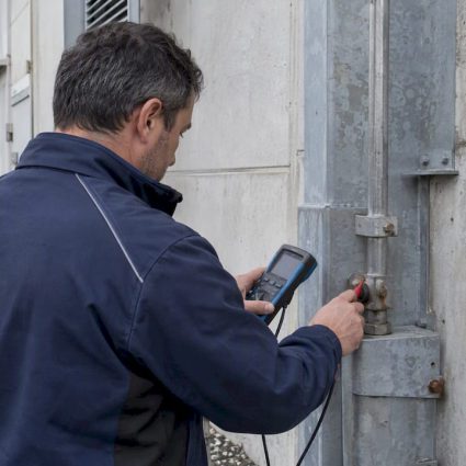
Handheld four-terminal earth testers (such as the Fluke 1625-2 or equivalent) perform Wenner array measurements in the field. The same instrument verifies installed earth resistance after electrode placement. These measurements are mandatory inputs, not optional checks.
Rolling-sphere calculators and spreadsheets:
For straightforward rectangular buildings, a rolling-sphere spreadsheet is sufficient. The engineer inputs building dimensions, roof height, and sphere radius, and the sheet outputs maximum terminal spacing and required terminal height. Several national lightning protection associations publish free templates aligned with NFPA 780 geometry.
3D modeling packages:
For complex roofs, 3D modeling is the reliable path. Tools such as AutoCAD with custom rolling-sphere scripts, or dedicated LPS design software, allow the engineer to visualize the protected volume and identify gaps that a 2D sketch would miss. The 3D model output — a rendered protected-volume overlay on the roof plan — is also the clearest deliverable for owner review and permitting.
On validation: a 3D rolling-sphere model is not just a visualization aid. For a roof with multiple levels, plant rooms, and rooftop HVAC units, the model is the only reliable way to confirm that every point on every surface falls inside the protected volume. Export the model output as a PDF overlay and include it in the design package alongside the calculation spreadsheet.
Manufacturer-supplied resources are also practical references. Indelec’s lightning protection system application pages include design examples for downconductor specification, earthing coordination, and integration with existing electrical infrastructure — useful as a cross-check against your own calculations.
Indelec Prevectron3: installation checks and field validation
The Prevectron3 is Indelec’s ESE (Early Streamer Emission) air terminal, built around OptiMax patented technology. For engineers specifying ESE devices, the practical placement considerations differ from conventional Franklin rod arrays: ESE terminals claim an extended protection radius based on their advance streamer emission time (ΔT), which manufacturers document in test reports. Engineers should treat manufacturer-published efficiency data as a design input and verify it against the rolling-sphere or accepted test methods before reducing terminal count below what a conventional calculation would require.
Installation checklist for Prevectron3 and equivalent ESE terminals:
- Mount at the structure’s highest point, or at the highest point of each protected zone on a multi-level roof
- Verify fixing method at the roof ridge or mast: the mount must resist mechanical loads specified in the product data sheet (wind, ice)
- Conductor attachment spacing along downconductors: follow NFPA 780 and manufacturer guidance (typically every 1 m on vertical runs, every 0.5 m on horizontal)
- Maintain minimum separation distance from metallic building elements to prevent side-flash
- Confirm mechanical clearances around the terminal head: no obstruction within the manufacturer’s specified radius
- Attach the product label and certificate to the terminal or to the project folder; the Prevectron3 certificate of guarantee is the document to request from the installer
Certification evidence to collect at handover:
- UL listing or equivalent product test certificate
- Manufacturer’s installation report confirming mounting method and conductor routing
- Measured earth resistance test result (post-installation)
- Photographic record of conductor routing, fixing points, and bonding connections
Indelec’s step-by-step technical installation guide covers mechanical fixing sequences, conductor attachment details, and the on-site checks installers should complete before sign-off. Engineers should specify these steps as contractual acceptance criteria, not leave them to installer discretion.
Testing, inspection, and maintenance: what the standards require
A correctly dimensioned LPS that is never tested or maintained will degrade. Corrosion at connections, loosened fixings, and soil drying all push earth resistance above acceptable limits over time.
Mandatory and recommended tests
Soil resistivity (Wenner method): conducted before design, not after. The result drives electrode sizing. Re-test if the site is significantly disturbed (excavation, drainage changes).
Earth resistance verification: measure after installation and before system commissioning. The practical target is below 10 Ω where practicable. Use a fall-of-potential or clamp-on method; the clamp-on method is faster for routine re-testing on existing systems.
Conductor continuity: verify electrical continuity from each air terminal through its downconductor to the earth electrode. A break anywhere in that path means the terminal is effectively disconnected.
Visual inspection: check all fixings, clamps, and conductor runs for corrosion, mechanical damage, and displacement. Pay particular attention to roof penetrations and conductor bends, where water ingress and fatigue cracking are most common.
Acceptance criterion: NFPA 780 and IEC 62305-3 both treat earth resistance as a design target rather than a fixed universal pass/fail threshold, but a practical target of less than 10 Ω is widely used in project specifications and is consistent with earthing design guidance for paratonnerre installations. If post-installation measurement exceeds this target, the remediation sequence is: add electrodes to the array, increase electrode depth, or engage a deep earth grounding service for high-resistivity soils.
Recommended inspection cadence
- Annual: visual inspection of all terminals, conductors, fixings, and bonding connections
- Every 3–5 years: full electrical test (earth resistance, conductor continuity, SPD condition check)
- After any significant lightning event: immediate visual and electrical check before returning the system to service
- After major building works: re-test earth resistance and verify that construction activity has not disturbed conductors or electrodes
The part of LPS design most engineers underestimate
Most engineers spend the bulk of their time on the geometry: rolling the sphere, placing terminals, counting downconductors. That work matters, but the calculation is rarely where a system fails. The failure points are almost always in the earthing system and in the documentation.
An LPS with a perfectly computed protected volume and a 25 Ω earth resistance is not a functioning system. The lightning current has nowhere to go. Yet earth resistance testing is routinely treated as a formality, conducted once at commissioning and never revisited. Soil resistivity changes seasonally, electrodes corrode, and construction activity disturbs buried conductors. A system that passed at commissioning may be well above 10 Ω five years later, with no one aware of it.
The second underestimated failure is documentation. A UL Master Label requires test records. An insurance claim after a strike requires proof the system was designed and maintained to standard. Engineers who treat the design package as a box-checking exercise, rather than a live project record, leave their clients exposed. The soil resistivity test result, the post-installation earth resistance measurement, and the product certification documents are not administrative overhead. They are the evidence that the system works.
The conventional advice to “follow the standard” is correct but incomplete. Following NFPA 780 for geometry while neglecting the earthing verification and documentation requirements produces a system that looks compliant on paper and may not perform when it matters.
Indelec: from calculation to certified installation
Sizing a lightning protection system correctly is one part of the job. Getting it installed, tested, and documented to a standard that holds up under inspection and insurance review is the other.

Indelec has been engineering and installing lightning protection systems since 1955, with projects across industrial, commercial, and public infrastructure sectors worldwide. The Prevectron3 ESE air terminal, built on OptiMax technology, is backed by manufacturer placement guidance, test certificates, and a certificate of guarantee that belongs in every project handover folder. Beyond the hardware, Indelec’s engineering team provides risk assessment, full system design, installation supervision, and post-installation testing, covering every step from Ng data collection to the final earth resistance record. For projects where standard electrode arrays cannot reach the 10 Ω target, Indelec’s deep earth grounding service provides the remediation path. Contact Indelec to request a technical consultation or a system design review for your next project.
Sources
- Paratonnerres : rôle, installation et réglementation
- Plan d’implantation des paratonnerres (annexes PDF)