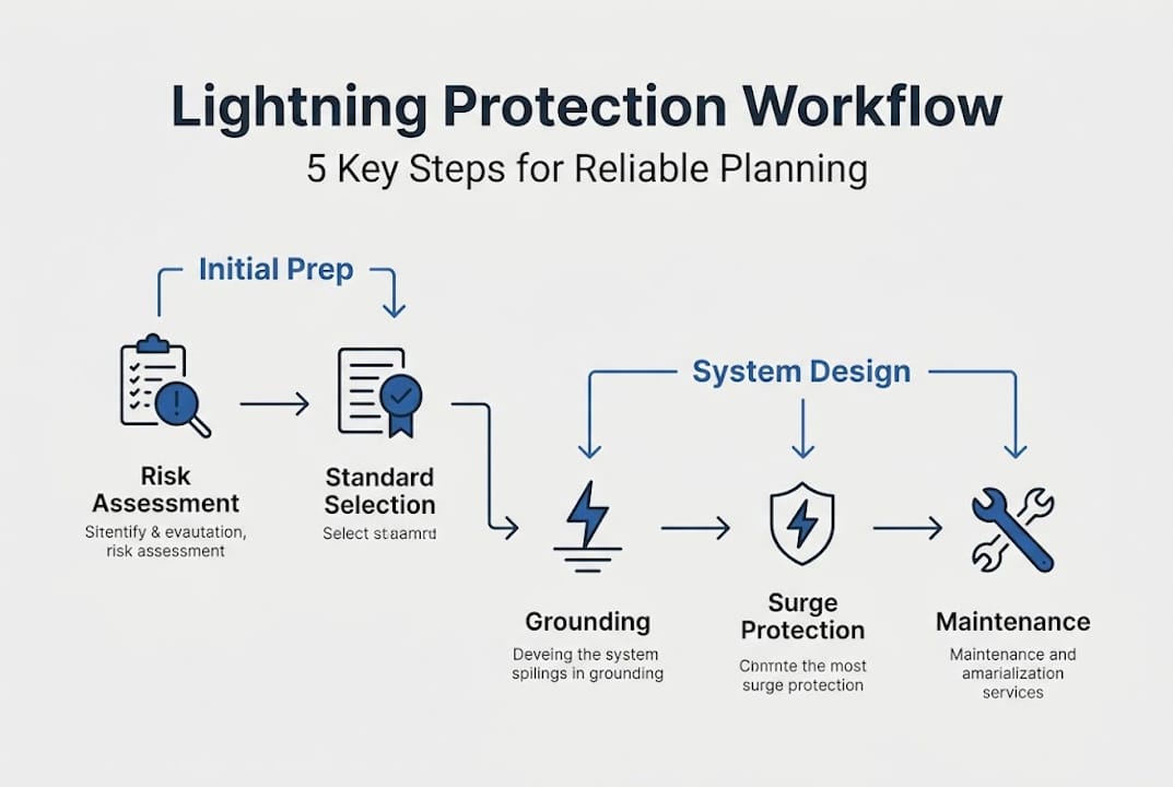
Optimize your lightning protection planning workflow: 5 key steps

TL;DR:
- A structured lightning protection workflow from risk assessment to maintenance is essential for facility safety.
- Proper grounding, accurate soil resistivity measurement, and adherence to standards ensure effective system performance.
- Regular testing, documentation, and expert support prevent costly failures and ensure compliance.
A single lightning strike can shut down an entire industrial facility for days, triggering equipment losses, regulatory fines, and serious safety violations. For facility managers and safety officers, the difference between a costly incident and a near-miss often comes down to one thing: a structured, standards-compliant lightning protection planning workflow. Without it, you’re guessing. With it, you have a repeatable process that protects people, assets, and your organization’s compliance record. This guide walks you through each critical stage, from risk assessment to annual maintenance, so you can build or audit your protection plan with confidence.
Table of Contents
- Understanding standards and risk assessment
- Designing external lightning protection systems
- Integrating internal lightning protection and surge controls
- Installation, verification, and maintenance workflow
- Expert perspective: What most lightning planning guides miss
- Next steps: Industry-leading solutions for lightning protection
- Frequently asked questions
Key Takeaways
| Point | Details |
|---|---|
| Start with risk assessment | Follow IEC 62305 or NFPA 780 standards for thorough risk analysis before any design work. |
| Design robust external protection | Use air terminations, spacing, and low-resistance grounding to meet facility needs and compliance. |
| Integrate surge devices and bonding | Install multiple levels of SPDs and ensure equipotential bonding to protect internal systems. |
| Verify and maintain regularly | Test, inspect, and maintain your system annually to guarantee safety and compliance. |
| Leverage expert insights | Utilize soil resistivity measurements and AI-powered calculations to improve accuracy. |
Understanding standards and risk assessment
Every effective lightning protection plan starts with the same foundation: understanding which standards apply to your site and conducting a rigorous risk assessment. Skip this step, and everything downstream is built on assumptions.
The two dominant frameworks are IEC 62305 and NFPA 780. A lightning protection planning workflow begins with a risk assessment using IEC 62305-2 or NFPA 780 Annex L to determine whether protection is needed and what Lightning Protection Level (LPL I through IV) is required. LPL I offers the highest protection and is typically required for facilities with explosive atmospheres, hospitals, or critical infrastructure. LPL IV is the baseline for lower-risk structures.
The two standards serve different purposes. IEC 62305 uses risk-based LPL selection, while NFPA 780 focuses on installation details for US compliance. In practice, use IEC 62305 for the planning and design phase, and NFPA 780 to verify your installation meets US code requirements. Our lightning standards reference covers both frameworks in detail.
The risk assessment itself follows a structured process:
- Site survey: Document building dimensions, construction materials, and occupancy type
- Hazard identification: Evaluate nearby structures, elevated terrain, and historical strike data
- LPL calculation: Apply the IEC 62305-2 formula to determine risk level and required protection class
- Review against thresholds: Compare calculated risk to tolerable risk values defined in the standard
A practical risk assessment guide can help you structure this process for your specific facility type. For larger infrastructure projects, the infrastructure lightning protection guide provides additional context on multi-site assessments.
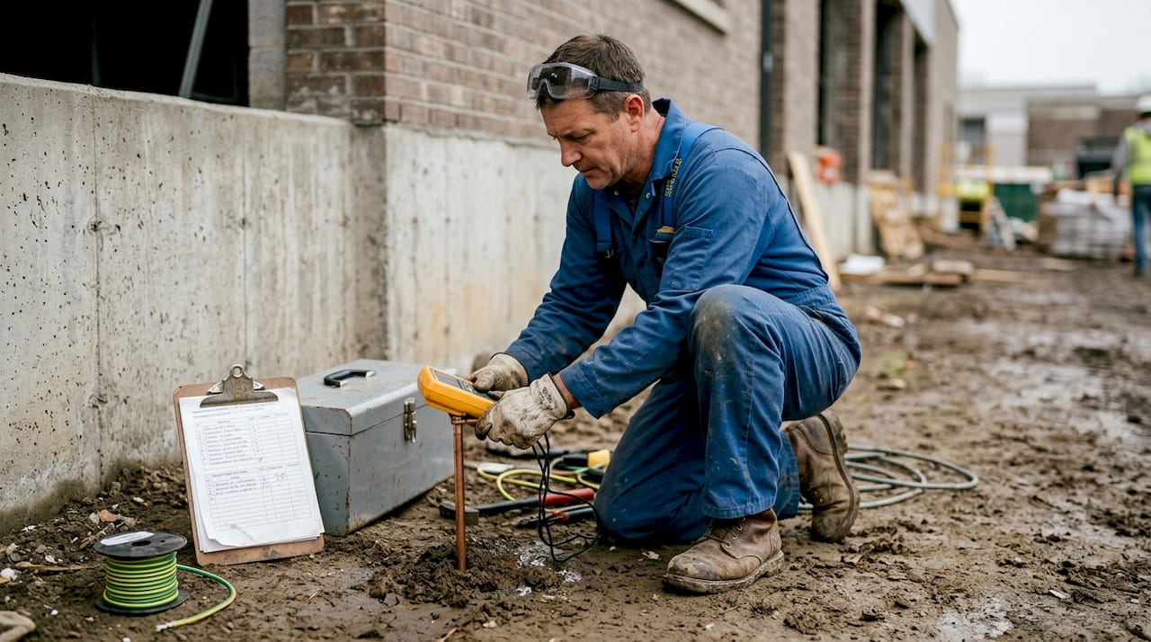
One factor that often gets overlooked at this stage: soil resistivity. It directly affects grounding system design, and measuring it before you finalize your risk assessment saves significant rework later. An external risk assessment overview confirms this is a common gap in standard practice.
| LPL | Protection efficiency | Typical application |
|---|---|---|
| I | 98% | Explosive/critical facilities |
| II | 95% | Industrial plants, hospitals |
| III | 90% | Commercial buildings |
| IV | 80% | Residential and low-risk structures |
Pro Tip: Measure site soil resistivity before finalizing your grounding design. Values above 1,000 ohm-meters may require deep earth grounding or chemical enhancement to meet resistance targets.
Designing external lightning protection systems
With risk assessed and standards understood, the next step is designing a robust external lightning protection system (LPS). This is where engineering decisions directly determine how well your facility handles a direct strike.
The external LPS has three core components: air terminations, down conductors, and the grounding system. Design the external LPS using air terminations (rods, mesh, or rolling sphere method), down conductors spaced per LPL (for example, 15 meters for LPL III), and grounding with a target resistance below 10 ohms.
Choosing the right air termination method depends on your structure:
- Franklin rods: Best for isolated structures or rooftop equipment with defined strike points
- Mesh conductors: Suitable for flat roofs and structures requiring uniform protection coverage
- Rolling sphere method: Used to verify coverage gaps; the sphere (radius varies by LPL) must not touch unprotected surfaces
- Early streamer emission (ESE) terminals: Offer extended protection radius, reducing the number of air terminals needed on complex structures
Down conductor spacing is non-negotiable. For LPL I, conductors must be spaced no more than 10 meters apart. For LPL III, that spacing extends to 15 meters. Reducing spacing increases protection but also cost, so your LPL calculation directly drives this budget decision.
Grounding is where many designs fall short. The target is below 10 ohms resistance per grounding electrode, and in high-resistivity soils, that requires deep earth electrodes or a ring earth electrode around the structure’s perimeter. Our lightning protection system applications page covers grounding configurations for various facility types, and our architectural protection solutions address aesthetic integration for commercial buildings.
| Method | Best use case | Coverage radius |
|---|---|---|
| Franklin rod | Isolated structures | Up to 20m (LPL I) |
| Mesh conductor | Flat or complex roofs | Full surface coverage |
| ESE terminal | Large or complex sites | Up to 107m (per model) |
| Rolling sphere | Verification tool | LPL-dependent radius |
Pro Tip: Always route down conductors in straight, vertical runs. Sharp bends create impedance spikes during a strike, which can cause side flashing to nearby metallic structures or internal systems.
Integrating internal lightning protection and surge controls
Now that external defenses are in place, let’s focus on internal protections and surge controls. This layer is often underestimated, yet it’s where most equipment damage actually occurs.
Lightning doesn’t have to strike your building directly to destroy sensitive electronics. Indirect strikes within several kilometers generate electromagnetic pulses that travel through power lines, data cables, and metallic pipework. That’s why internal protection with Surge Protection Devices (SPDs) is essential: Type 1 at the service entry, Type 2 at distribution panels, Type 3 at individual equipment, plus equipotential bonding throughout.
Here’s how to structure your SPD deployment:
- Type 1 SPDs: Installed at the main service entry point, these handle direct lightning current injection and are mandatory when an external LPS is present
- Type 2 SPDs: Placed at sub-distribution boards to limit residual surges that pass through Type 1 devices
- Type 3 SPDs: Installed directly at sensitive equipment (servers, PLCs, medical devices) for fine protection
- Equipotential bonding: All metallic services entering the building (water, gas, data, power) must be bonded to a common reference point to eliminate dangerous potential differences
Common mistakes in this stage include omitting Type 3 devices for critical equipment, bonding only power conductors while ignoring data lines, and failing to document SPD locations for future maintenance.
Safety note: Internal lightning protection is not optional for facilities with sensitive control systems, process automation, or data infrastructure. A single unprotected surge path can cascade through an entire network, causing failures that take days to diagnose and repair.
Our building lightning safety guide covers SPD selection criteria and bonding requirements in greater depth.
Pro Tip: After installation, test every bonding connection with a low-resistance ohmmeter and document the measured values. This baseline record is essential for future inspections and insurance audits.
Installation, verification, and maintenance workflow
With both external and internal systems designed, ensuring proper installation, verification, and maintenance cements protection for your facility. Design quality means nothing if installation is rushed or undocumented.
Installation requires qualified professionals, straight down conductors with a bend radius greater than 20 centimeters, dedicated grounding per conductor, and full documentation of every component and connection.
Follow this installation sequence:
- Grounding first: Install and test all earth electrodes before mounting above-grade components. Confirm resistance targets are met before proceeding.
- Down conductors: Route from air terminations to ground electrodes using the shortest, straightest path. Secure at regular intervals to prevent mechanical damage.
- Air terminations: Mount per design drawings, verifying rolling sphere compliance at each point.
- Internal bonding and SPDs: Install from the service entry inward, testing each stage before energizing.
- Final continuity test: Verify electrical continuity across the entire external LPS from air terminal to earth electrode.
Verification doesn’t end at commissioning. Testing includes continuity, ground resistance, inspection, commissioning, and annual maintenance as required by standards. Your ongoing maintenance checklist should include:
- Annual ground resistance measurement at each electrode
- Visual inspection of all conductors, clamps, and connections for corrosion or mechanical damage
- SPD status indicator checks and replacement of any triggered devices
- Review of documentation against any facility changes or additions
- Update of the risk assessment if the structure or occupancy has changed
Compliance reminder: Annual maintenance is not just best practice. Most insurance policies and local regulations require documented inspection records to maintain coverage and compliance status.
Our installation workflow guide and facility workflow guide provide templates for commissioning documentation. For ongoing support, our installation and maintenance services team works with facility managers across industrial and commercial sectors.
Expert perspective: What most lightning planning guides miss
Most lightning protection guides focus on what to do. Few address why so many well-intentioned workflows still produce underperforming systems. After decades of working on industrial and infrastructure projects globally, the pattern is consistent: the failures are rarely in the design documents. They’re in the data that was never collected.
Soil resistivity is the clearest example. Facilities skip this measurement to save time, then discover post-installation that their grounding system can’t reach the required resistance. Retrofitting deep earth electrodes into a completed facility is expensive and disruptive.
The second gap is over-reliance on manual standards review. IEC 62305-2 risk calculations involve multiple variables, and manual errors are common. AI tools accelerate IEC risk calculations by 90%, improving accuracy over manual methods. These tools are not experimental. They’re practical and available now.
Our contractor lightning guide outlines how to integrate both soil testing and calculation tools into your standard workflow. Revisit your site data. Automate what can be automated. That’s where real compliance gains are found.
Next steps: Industry-leading solutions for lightning protection
Understanding the workflow is the first step. Executing it with proven technology and expert support is what separates compliant facilities from vulnerable ones.
Indelec’s Prevectron3 air terminals are engineered for complex industrial and commercial structures, offering extended protection radius and simplified installation. Our system application solutions cover the full range of facility types, from manufacturing plants to data centers. For sites with challenging soil conditions, our deep earth grounding services ensure your grounding system meets resistance targets regardless of geology. With Indelec’s technical team behind your project, you get more than products. You get a compliance-ready system backed by 70 years of field experience.
Frequently asked questions
What standards are mandatory for lightning protection system planning?
IEC 62305 uses risk-based LPL selection and is globally recognized for planning, while NFPA 780 is essential for installation compliance in the US. Most international projects reference IEC 62305 as the primary design standard.
How is soil resistivity measured and why does it matter?
Soil resistivity is measured using a Wenner four-pin ground resistance meter and directly determines whether your grounding system can achieve the required sub-10-ohm resistance. Measuring soil resistivity before design prevents costly grounding retrofits after installation.
What are the main components of an external lightning protection system?
An external LPS includes air terminations, down conductors spaced per LPL, and a grounding system targeting below 10 ohms resistance. The external LPS design must be verified using the rolling sphere method to confirm full structural coverage.
How often should lightning protection systems be tested and maintained?
Annual testing and maintenance are required by IEC 62305 and NFPA 780 to verify continuity, ground resistance, and SPD functionality. Documented records from these inspections are typically required for insurance and regulatory compliance.