Step-by-step guide to infrastructure lightning protection
TL;DR:
- Proper lightning protection systems are essential to prevent costly industrial downtime and control system damage.
- Risk assessment considers location, facility type, and asset criticality to determine appropriate protection levels.
- Regular maintenance and verification are crucial for system effectiveness over its service life.
A single lightning strike can halt a production line, destroy control systems, and trigger days of costly downtime. For industrial facilities, that’s not a hypothetical scenario — it’s a documented risk that facility managers face every storm season. A properly designed and installed lightning protection system (LPS) is your primary defense. This guide walks you through every phase: risk assessment, system design, installation, and ongoing verification. Every recommendation here aligns with recognized standards, including NFPA 780, so you can implement with confidence and regulatory backing.
Table of Contents
- Assessing facility risk and gathering requirements
- Planning and design of the lightning protection system
- Installation: step-by-step process and best practices
- Verification, maintenance, and troubleshooting
- What most guides miss about lightning protection systems
- Get expert support for lightning protection installations
- Frequently asked questions
Key Takeaways
| Point | Details |
|---|---|
| Risk-based planning | Begin protection projects with a thorough risk assessment and reference to major standards like NFPA 780 and IEC 62305. |
| Systematic installation | Follow structured, stepwise installation to properly integrate all lightning protection system components. |
| Ongoing verification | Regular testing and maintenance are essential to ensure lasting system effectiveness and facility safety. |
| Expert support matters | Complex projects and high-risk environments benefit from certified expertise and specialized solutions. |
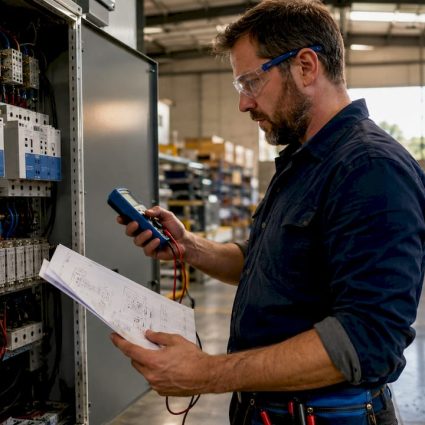
Assessing facility risk and gathering requirements
Before specifying a single component, you need a clear picture of your facility’s exposure. Lightning risk isn’t uniform. A chemical plant in Florida faces a fundamentally different threat profile than a warehouse in the Pacific Northwest. Start by mapping three variables: geographic location (ground flash density), facility type (flammable materials, sensitive electronics, occupied structures), and asset criticality (what fails if lightning hits).
Two major standards govern how you frame this assessment. NFPA 780 follows a prescriptive approach, specifying minimum requirements based on structure type. IEC 62305 takes a risk-based approach, calculating the probability of loss against tolerable risk thresholds. For complex industrial sites, IEC 62305’s quantitative method often produces a more accurate protection specification. Our risk assessment guide provides a practical framework for running this calculation.
Once you’ve assessed risk, you select a Lightning Protection Level (LPL). These levels define the design parameters of your entire system:
- LPL I: Designed for 200kA maximum current, 98% effectiveness. Use for the highest-risk facilities: explosive atmospheres, critical infrastructure, data centers.
- LPL II: 150kA, 95% effectiveness. Appropriate for hospitals, large industrial plants, and fuel storage.
- LPL III: 100kA, 90% effectiveness. Suitable for commercial buildings and mid-risk industrial sites.
- LPL IV: 100kA, 80% effectiveness. Minimum protection for low-risk, non-critical structures.
The gap between LPL I and LPL IV is significant: 18 percentage points of protection effectiveness. For a facility running continuous operations, that difference translates directly into financial and safety exposure.
| Feature | NFPA 780 | IEC 62305 |
|---|---|---|
| Approach | Prescriptive | Risk-based |
| Best for | US compliance | Complex/global sites |
| LPL system | Yes | Yes (LPL I-IV) |
| Risk quantification | Limited | Detailed |
| Surge protection | Included | Included |
You’ll also need to inventory your materials before design begins: air terminals (lightning rods), down conductors, grounding electrodes, surge protective devices (SPDs), and equipotential bonding components. Refer to our overview of lightning standards to confirm material specifications for your jurisdiction.
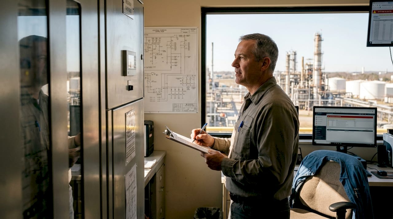
Planning and design of the lightning protection system
With requirements in hand, design translates risk data into a physical protection layout. Every component placement decision affects system performance, so precision here prevents costly rework later.
The five core LPS components you’ll position in your design are:
- Air terminals: Intercept lightning before it strikes the structure
- Down conductors: Carry current safely to ground
- Grounding electrodes: Dissipate energy into the earth
- Surge protective devices (SPDs): Block transient overvoltages from entering electrical systems
- Equipotential bonding: Eliminate dangerous voltage differences between metallic systems
For air terminal placement, IEC 62305 uses the rolling sphere method, which simulates a sphere of radius 20 to 60 meters (depending on LPL) rolling across the structure. Any point the sphere touches without contacting an air terminal is unprotected. This method is especially useful for irregular rooftop geometry common in industrial facilities. You can review LPS application examples to see how this plays out on real structures.
High-risk environments require additional design measures. Explosive atmospheres, tank farms, and tall structures (over 60 meters) need grounding separation of at least 3 meters from accessible areas, along with insulated LPS conductors to prevent side-flash hazards. For sites with poor soil conductivity, deep earth grounding may be necessary. Our earth grounding drilling service addresses this for facilities where surface grounding alone won’t achieve the required resistance values.
For tall structures or sites where roof-mounted terminals aren’t practical, mast systems and catenary (overhead wire) configurations extend coverage effectively. A highly sensitive site design example illustrates how these configurations are applied in practice.
Pro Tip: Always run your rolling sphere and grounding separation calculations using the current edition of your governing standard. Outdated calculations are one of the most common sources of non-compliance during third-party audits.
Document every design decision with drawings and calculations. Regulators and insurers will ask for this documentation, and it becomes the baseline for future maintenance inspections.
Installation: step-by-step process and best practices
A well-designed system only performs if it’s installed correctly. Errors in mounting, conductor routing, or bonding can render even the best design ineffective.
Follow this sequence for a compliant, effective installation:
- Install air terminals first. Mount rods or early streamer emission (ESE) devices at the positions specified in your design. Secure all mounts to resist wind loading for your region.
- Route down conductors. Run conductors from each air terminal to ground level. Minimize sharp bends (keep bend radius above 200mm) since tight angles create impedance that reduces current flow efficiency.
- Install grounding electrodes. Drive rods or lay ring electrodes as designed. Measure ground resistance immediately after installation. Target values are typically below 10 ohms, though some standards require below 5 ohms for critical facilities.
- Install surge protective devices. Place Type 1 SPDs at the main service entrance, Type 2 at distribution panels, and Type 3 at sensitive equipment. Each type handles a different level of residual surge energy.
- Complete equipotential bonding. Connect all metallic structures, piping, cable trays, and equipment frames to the LPS. This step is frequently underestimated but is critical for preventing step-voltage and touch-voltage hazards.
UL-listed LPS components and certified installers are mandated under NFPA 780. Using non-listed components or uncertified labor isn’t just a compliance risk — it’s a liability exposure if a strike causes injury or property damage. Our lightning protection services include certified installation teams experienced in industrial environments.
Safety reminder: Never work on or near energized electrical equipment during installation. Coordinate with your electrical team to isolate circuits before bonding connections are made to distribution systems.
Pro Tip: Create a phase-by-phase installation checklist tied directly to your design drawings. Sign off each phase before moving to the next. This creates a defensible compliance record and catches errors before they’re buried under finished construction.
For specialized environments like open-air facilities, our work on advanced LPS for golf courses demonstrates how installation principles adapt to non-standard site conditions.
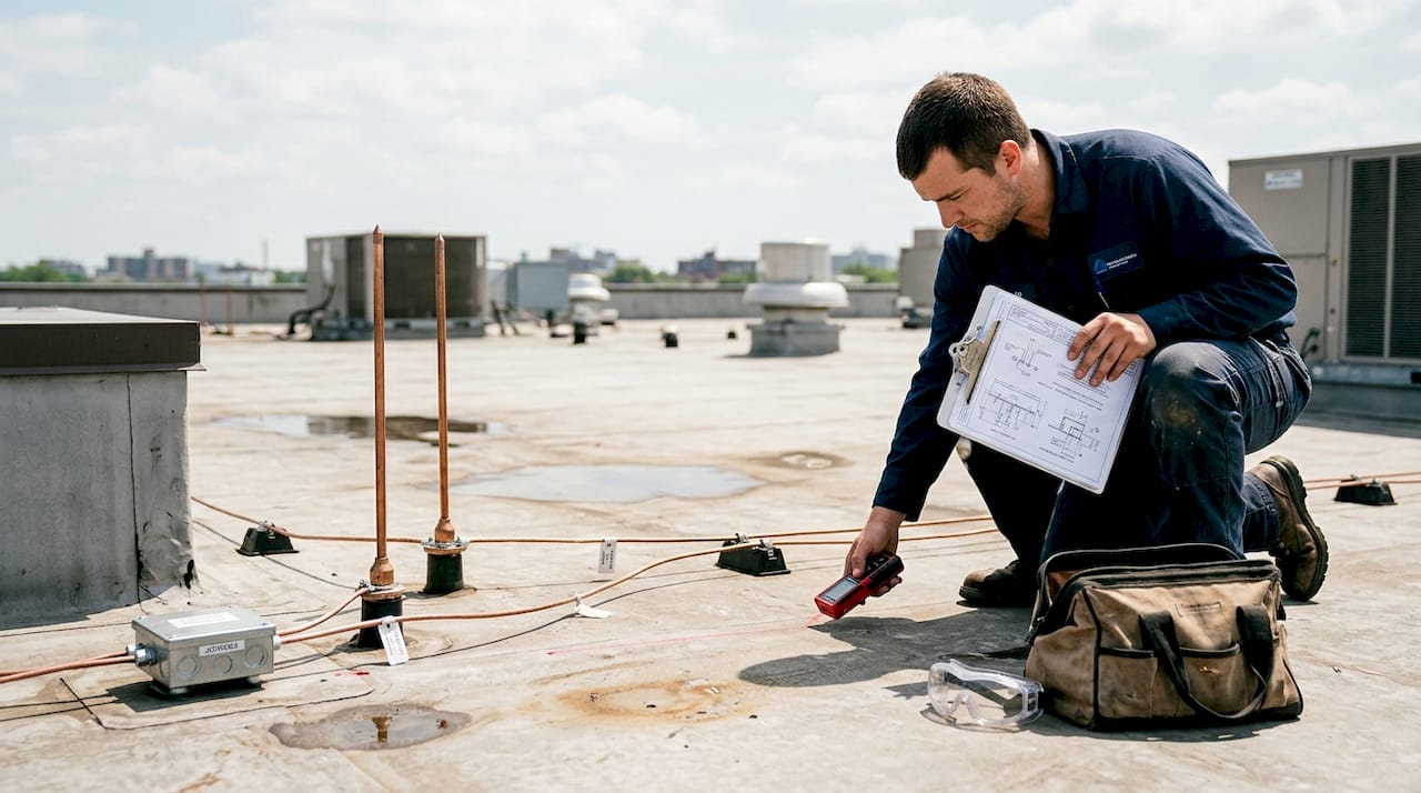
Verification, maintenance, and troubleshooting
Installation completion is a milestone, not a finish line. Lightning protection systems degrade over time, and a system that passed initial inspection may fail years later without proper maintenance.
Begin with initial verification tests immediately after installation:
- Ground resistance test: Confirm all electrodes meet the specified resistance threshold using a fall-of-potential or clamp-on tester
- Continuity test: Verify unbroken conductor paths from every air terminal to every grounding electrode
- Visual inspection: Confirm all connections are tight, conductors are properly routed, and SPDs are correctly installed and labeled
- SPD function check: Verify status indicators on all installed surge devices
NFPA 780 and IEC 62305 both outline maintenance and periodic verification requirements. Most industrial facilities should schedule full inspections annually, with visual checks after any significant storm event.
Common issues found during maintenance include:
- Corroded or mechanically damaged conductors, especially at roof penetrations and underground transitions
- Loose bonding clamps caused by thermal expansion cycles
- SPDs that have absorbed surges and reached end-of-life without triggering visible indicators
- Air terminals shifted out of position by wind or rooftop equipment changes
When troubleshooting a suspected system failure, work through this sequence:
- Retest ground resistance at each electrode. Compare to original installation values.
- Perform continuity testing on every conductor run. Identify any open circuits.
- Inspect all mechanical connections visually and torque-check bonding clamps.
- Replace any SPDs showing fault indicators or that have exceeded their rated surge count.
- Review any structural or rooftop changes since the last inspection that may have altered coverage geometry.
Our installation project in Iraq illustrates how systematic verification protocols were applied in a demanding industrial environment with challenging soil conditions.
Pro Tip: Keep a dedicated logbook for every inspection, test result, and component replacement. When a strike event occurs, this record is your first tool for diagnosing whether the system performed as designed.
What most guides miss about lightning protection systems
Most installation guides treat standards as complete answers. They’re not. Standards define minimums, not optimal protection. NFPA 780 has been criticized in IEEE research as inadequate for complex risk scenarios, with IEC 62305 preferred internationally for its quantitative risk framework.
The real gap shows up in edge cases: facilities that straddle two risk categories, structures that have been modified since original LPS design, or sites where soil conditions vary dramatically across the grounding field. No standard fully accounts for these situations. That’s where engineering judgment, informed by hands-on testing and real-world strike data, fills the gap.
We’ve seen facilities that were technically compliant but practically under-protected because the LPS design was never updated after a building expansion. We’ve also seen over-engineered systems on low-risk structures that consumed budget without adding meaningful protection. The standard is your floor, not your ceiling. For airports and similarly complex infrastructure, our airport LPS guidelines show how expert-driven design goes beyond prescriptive compliance to address real operational risk.
Get expert support for lightning protection installations
Designing and installing an LPS that genuinely protects your facility requires more than following a checklist. It requires product selection aligned to your specific risk level, installation by certified professionals, and a maintenance program that keeps the system performing over its full service life.
Indelec’s Prevectron3 technology delivers advanced early streamer emission performance for industrial and infrastructure applications. Our ESE lightning rod research confirms higher efficiency compared to conventional Franklin rods in complex site conditions. From system design and application through deep earth grounding drilling for challenging soil environments, Indelec provides end-to-end support for facilities that can’t afford to get protection wrong.
Frequently asked questions
Which standards should industrial facilities follow for lightning protection?
Facilities in the US should follow NFPA 780, while international or complex sites benefit from IEC 62305’s risk-based methodology for more precise protection specifications.
How can you verify lightning protection effectiveness after installation?
Perform ground resistance tests, continuity checks, and visual inspections immediately after installation, then repeat annually per NFPA 780 and IEC 62305 verification requirements.
What makes surge protective devices (SPDs) important in LPS?
SPDs Type 1 through 3 are core LPS components that block transient overvoltages from traveling through your facility’s electrical systems after a strike, protecting sensitive equipment and control systems.
How do design needs change for explosive or tall sites?
Explosive atmospheres and structures over 60 meters require grounding separation of at least 3 meters from accessible areas and insulated LPS conductors to prevent side-flash hazards, as specified in IEC 62305.