Why Grounding Is Important for Facility Safety
TL;DR:
- Grounding connects electrical systems to earth to stabilize voltage but cannot reliably clear faults due to high soil resistance. Bonding creates low-impedance paths between metal parts, enabling protection devices to trip within safety timeframes. Proper maintenance and design ensure that both functions work together to prevent electrical shocks, fires, and equipment damage.
Grounding is the process of connecting an electrical system to the earth to stabilize voltage and create the fault current path that protective devices need to operate. Without it, a live conductor touching metal equipment leaves workers exposed to lethal shock, fires can ignite from sustained arcing, and sensitive electronics face destruction from uncontrolled surges. The industry term is protective earthing, and understanding why grounding is important separates facilities that meet compliance on paper from those that are genuinely safe. This article explains the mechanics, the standards, and the practical steps facility managers need to act on.
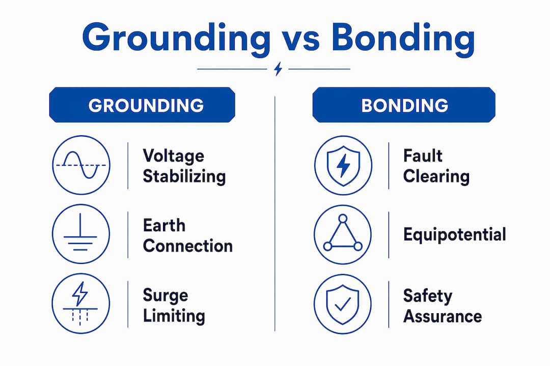
Why grounding is important: grounding vs. bonding explained
The single most common misconception in facility electrical safety is treating grounding and bonding as the same thing. They are not, and NEC 250.4 distinguishes system grounding from bonding with precision that every facility manager should understand.
Grounding connects the electrical system neutral and equipment enclosures to an earth electrode. Its primary job is voltage stabilization. It limits the rise of voltage from lightning surges or line faults and provides a reference point for the system. What it does not do is reliably clear a fault. Earth is a poor conductor. The resistance of a ground rod and surrounding soil is far too high to carry the fault current needed to trip a breaker in milliseconds.
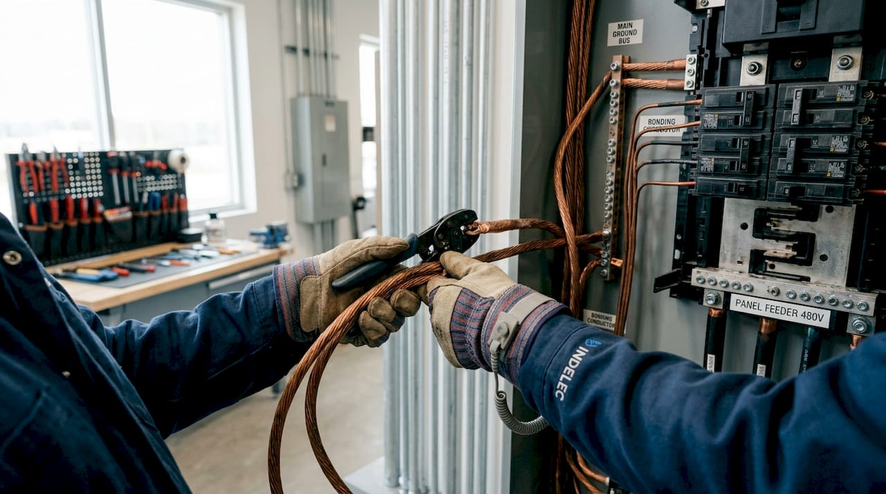
Bonding is the low-impedance connection between all metal parts, equipment enclosures, conduit, and structural steel, tied back to the power source. This is the path that actually carries fault current when a live wire contacts metal. Bonding enables the fault current path that trips breakers and clears faults before a person is harmed.
The practical consequences of confusing the two are serious:
- A facility installs a ground rod and assumes the system is safe.
- A fault occurs on a motor frame. The bonding conductor is corroded or missing.
- The fault current is too low to trip the breaker. The motor frame stays energized.
- A worker touches it and receives a shock.
Pro Tip:When auditing a facility, do not stop at confirming a ground rod is present. Trace every bonding conductor from equipment back to the main panel and verify continuity with a low-resistance ohmmeter. The ground rod is secondary to bonding integrity.
Grounding design for compliance requires both elements working together. Grounding stabilizes. Bonding clears. Neither is optional.
How grounding supports protective device operation and safety standards
The reason protective earthing is mandated by every major electrical code is mechanical. A breaker or fuse trips when current exceeds its rating. For that to happen during a fault, the fault current path must have low enough impedance to push enough current through the device. This is why bonding continuity and low impedance are performance requirements, not suggestions.
Standards set quantitative targets. BS 7671:2018 Table 41.1 requires automatic disconnection within 0.4 seconds for typical 230V circuits in TN systems. That 0.4-second window is not arbitrary. It reflects the threshold beyond which sustained contact with a live surface causes ventricular fibrillation in most adults. Meeting that target depends entirely on the impedance of the fault current loop being low enough to drive sufficient current through the protective device.
The sequence works as follows:
- A fault occurs. A live conductor contacts a metal enclosure.
- Current flows from the source, through the fault, through the bonding conductor, back to the transformer neutral.
- If bonding impedance is low, fault current is high. The breaker trips within 0.4 seconds.
- If bonding impedance is high due to corrosion, undersized conductors, or missing connections, fault current is low. The breaker does not trip. The enclosure stays live.
- Poor or absent earthing leaves hidden faults active, increasing shock risk, fire risk, and equipment damage.
The table below shows how grounding system condition directly affects safety outcomes:
| Grounding condition | Fault current level | Breaker response | Risk level |
|---|---|---|---|
| Low-impedance bonding intact | High | Trips within 0.4 seconds | Low |
| Corroded or partial bonding | Moderate | Delayed or no trip | Elevated |
| Missing bonding, ground rod only | Very low | No trip | Critical |
The implication for facility managers is direct. Compliance with NEC or BS 7671:2018 is not achieved by installing hardware. It is achieved by maintaining the impedance performance that the hardware was designed to deliver.
What are the grounding challenges in lightning protection design?
Lightning protection introduces grounding complexity that standard power system design does not. NFPA 780 requires interconnection among all grounding electrode systems, including lightning protection, power distribution, and communications, to maintain equipotential bonding across the facility. IEC 62305 carries the same requirement internationally.
The logic is sound. During a lightning strike, the potential of the earth electrode rises sharply. If the lightning protection ground and the power system ground are separate, a massive voltage difference appears between them for microseconds. That difference drives current through any connected equipment, destroying it. Interconnecting all grounds eliminates the voltage difference by raising all systems to the same potential simultaneously.
The complication arises from bonding topology. Multiple bonding points between lightning protection conductors and equipment grounds create parallel current paths. During a strike, lightning current splits across those paths, inducing voltages in loops formed by the conductors. Those induced voltages appear directly across the terminals of PLCs, variable frequency drives, and communication equipment, often at levels that exceed their protection ratings.
| Bonding approach | Effect on power fault clearing | Effect on lightning transients | Recommended for |
|---|---|---|---|
| Single-point bonding | Effective if conductor sizing is correct | Minimizes induced voltage loops | Facilities with sensitive electronics |
| Multi-point bonding | Effective | Increases circulating current risk | Simple industrial sites, low electronics density |
| No interconnection | Ineffective | Creates dangerous potential differences | Not recommended under any standard |
Pro Tip:For facilities running PLCs, SCADA systems, or precision instrumentation, commission a bonding topology review before installing or upgrading a lightning protection system. The cost of a design review is a fraction of replacing a control panel destroyed by an induced transient.
Facilities with lightning exposure need grounding systems designed to satisfy two separate objectives simultaneously: low-impedance fault clearing for power safety and equipotential bonding for surge management. These objectives can conflict if the design does not address both explicitly.
Practical steps to verify and maintain effective grounding
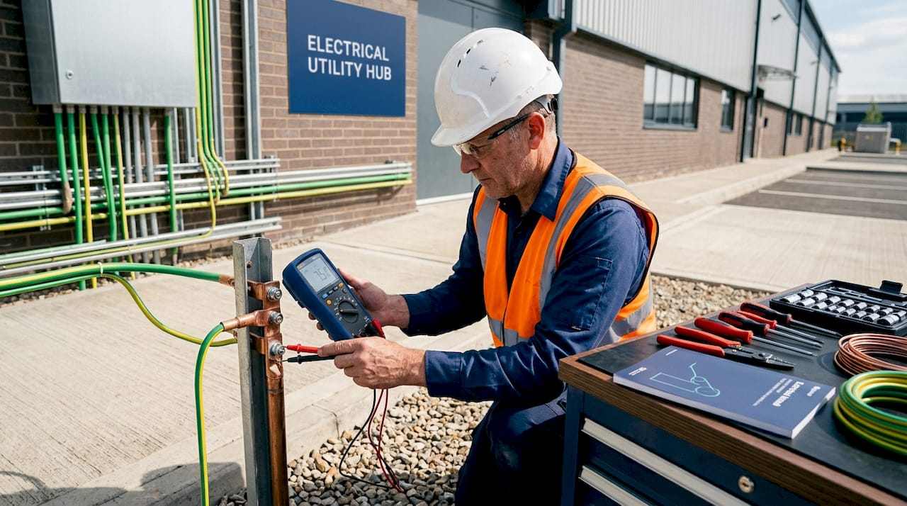
Confirming that a grounding system works requires more than a visual inspection. Measuring earth electrode resistance alone is insufficient. The critical measurement is the impedance of the complete fault current loop, from the source through the bonding conductors to the point of potential fault, because that value determines whether protective devices will trip within the required time.
Facility managers should prioritize the following verification steps:
- Earth fault loop impedance testing. Use a loop impedance tester at each distribution board and at representative points on the installation. Compare results against the maximum impedance values permitted by the applicable standard for the protective device installed.
- Bonding continuity checks. Measure resistance between all bonded metal parts and the main earthing terminal. Values above a few milliohms on short runs indicate a problem worth investigating.
- Visual inspection of bonding conductors. Look for corrosion at connections, mechanical damage to conductors, and missing bonds on equipment added after the original installation. New equipment is a common source of bonding gaps.
- Lightning protection system integration review. Verify that the lightning protection earth electrode is bonded to the main earthing terminal of the power system per NFPA 780 or IEC 62305, and that the bonding conductor is correctly sized.
- Documentation review. Confirm that grounding system records reflect the current installation. Facilities that have expanded or modified equipment often have grounding documentation that no longer matches reality.
Periodic inspection and testing by a qualified electrician should occur at intervals defined by the applicable standard and more frequently after any significant modification to the electrical installation or lightning protection system.
Pro Tip:Schedule grounding system testing after any major equipment addition, not just on a fixed calendar. A new motor, a server room expansion, or a rooftop HVAC unit can all introduce bonding gaps that the original installation did not have.
A lightning risk assessment should feed directly into grounding design decisions, particularly for facilities in high-keraunic zones or those housing critical infrastructure.
Key takeaways
Effective grounding requires low-impedance bonding continuity throughout the installation, not just the presence of a ground rod, because bonding is what enables protective devices to clear faults within the time limits that prevent injury.
| Point | Details |
|---|---|
| Grounding stabilizes, bonding clears | Earth electrodes limit voltage surges; bonding conductors carry fault current to trip breakers. |
| Disconnection time is the safety target | BS 7671:2018 requires fault clearing within 0.4 seconds; this depends on bonding impedance, not the ground rod. |
| Lightning protection adds complexity | NFPA 780 and IEC 62305 require all ground systems to be interconnected to prevent dangerous potential differences. |
| Single-point bonding protects electronics | Facilities with PLCs or SCADA systems should use single-point bonding topology to prevent induced transient damage. |
| Testing must go beyond visual checks | Earth fault loop impedance testing validates that protective devices will actually trip under real fault conditions. |
Grounding is not a checkbox. It is a performance requirement.
After nearly seven decades working with facilities across industrial, energy, and infrastructure sectors, Indelec has seen one pattern repeat itself more than any other: grounding systems that look correct on paper but fail in practice. The ground rod is there. The bonding conductors are installed. The paperwork is signed. Then a fault occurs, the breaker does not trip, and a worker is injured or a control room is destroyed.
The uncomfortable reality is that most grounding failures are invisible until something goes wrong. Corroded bonding connections, undersized conductors added during a facility expansion, or a lightning protection system bonded at multiple points to sensitive equipment grounds. None of these show up on a visual walk-through. All of them represent real risk.
What we have learned from designing and installing grounding and lightning protection systems across thousands of facilities is that the facilities with the best safety records treat grounding as a performance system, not a compliance formality. They test loop impedance. They review bonding topology when they add equipment. They integrate lightning protection design with power system earthing from the start, not as an afterthought.
The emergence of dense electronics in industrial environments, PLCs, variable frequency drives, distributed control systems, makes this more critical now than it was twenty years ago. These devices are far more vulnerable to induced transients than the relay-based controls they replaced. A grounding system designed only for shock protection will not protect them. Facilities need grounding systems designed to address surge management, fault clearing, and lightning transient control as three distinct but coordinated objectives.
Grounding is not a line item to minimize. It is the foundation on which every other electrical safety measure depends.
— Indelec
How Indelec can help you get grounding right

Indelec has specialized in electrical protection since 1955, with grounding system design and lightning protection at the core of every project. For facility owners and managers who need confidence that their installation meets NEC, IEC 62305, or NFPA 780 requirements, Indelec provides engineering assessments, system design, installation, and certification services. From lightning protection system design for complex industrial sites to deep earth grounding drilling where soil conditions make standard electrodes insufficient, Indelec’s technical teams deliver grounding solutions built for real-world performance. Contact Indelec to schedule a grounding system assessment for your facility.
FAQ
What is the difference between grounding and bonding?
Grounding connects the electrical system to an earth electrode to stabilize voltage and limit surges. Bonding connects metal parts and equipment back to the power source to create the low-impedance fault current path that trips protective devices.
Why does a ground rod alone not make a facility safe?
Earth has too high a resistance to carry the fault current needed to trip a breaker within the required disconnection time. NEC 250.4 explicitly states that earth is not an effective fault current path, making bonding continuity the critical safety element.
How often should grounding systems be tested?
Grounding systems should be tested at intervals defined by the applicable standard and after any significant modification to the electrical installation or lightning protection system. Visual inspection is not sufficient. Earth fault loop impedance testing is required to confirm protective device coordination.
Why does lightning protection affect grounding design?
Lightning protection systems must be bonded to the power system earth to prevent dangerous potential differences during a strike. However, multiple bonding points can create circulating currents that damage sensitive electronics, so bonding topology must be engineered carefully per IEC 62305 and NFPA 780.
What is the maximum disconnection time allowed for fault clearing?
BS 7671:2018 Table 41.1 sets a maximum disconnection time of 0.4 seconds for typical 230V circuits in TN systems. Achieving this requires the fault current loop impedance to be low enough to drive sufficient current through the protective device.