Protection System Verification: A 2026 Guide for Safety Officers

TL;DR:
- Protection system verification ensures each component meets specifications and performs correctly throughout system deployment.
- It requires passing three independent SIL gates per IEC 61511 and incorporating static, dynamic, and functional testing methods.
Protection system verification is defined as the systematic process of confirming that every element of a safety protection system meets its documented specifications and performs correctly under intended operating conditions. This definition matters because verification is not the same as validation. Verification differs from validation, which confirms top-level stakeholder needs; verification is ongoing throughout design and implementation. For safety officers and compliance managers in industrial facilities, understanding this distinction is the foundation of every audit-ready compliance program. Standards like IEC 61511 and IEC 60255 set the specific requirements your facility must meet.
What is a protection system verification, and why does it matter?
Protection system verification is the structured confirmation that each component and subsystem performs according to its design specification. It is not a single test at the end of a project. Verification is ongoing throughout design, installation, and commissioning, generating documented evidence at every stage.
The industrial stakes are high. A protection system that trips too slowly, fails to trip at all, or trips incorrectly can cause equipment damage, personnel injury, or regulatory shutdown. Verification catches these failures before they become incidents. That is why regulators and auditors treat verification records as primary evidence of due diligence.
The definition of protection system verification also carries a legal dimension. Facilities operating under IEC 61511 or national equivalents must demonstrate that safety instrumented functions achieve their required Safety Integrity Level (SIL). Without documented verification, that demonstration is impossible. Verification is therefore both a technical activity and a compliance obligation.
What are the key standards governing protection system verification?
Two standards define the regulatory floor for most industrial facilities: IEC 61511 and IEC 60255. Each addresses a different layer of the protection system, and compliance managers must understand both.
IEC 61511 governs safety instrumented systems in the process industries. It requires three independent SIL verification gates:
- Quantitative probability threshold: The calculated probability of failure on demand (PFDavg) must fall within the target SIL band.
- Systematic capability: Every device in the safety function must carry a certified systematic capability rating at or above the target SIL.
- Architectural hardware fault tolerance: The hardware configuration must meet the minimum fault tolerance requirements for the target SIL level.
All three gates must pass independently. Passing two out of three does not constitute compliance. This is the most common misunderstanding safety officers encounter during third-party audits.
IEC 60255 covers protection relays specifically. It sets requirements for functional assessment, accuracy testing, and documentation of relay performance. Facilities with electrical protection schemes, including those governed by electrical protection standards, must align relay testing procedures with IEC 60255 to produce audit-ready records.
The safety function life cycle under IEC 61511 also requires continuous verification. Modifications to any element of a safety function trigger a re-verification requirement. This means verification is not a project milestone. It is a permanent operational responsibility.
Pro Tip:Document the rationale for every verification decision, not just the pass/fail result. Auditors look for evidence of engineering judgment, not just numbers.
What are the main methods used in protection system testing?
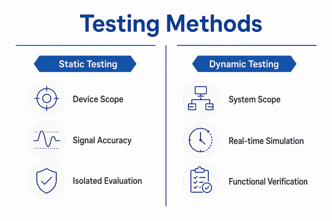
Protection system testing divides into two primary categories: static testing and dynamic testing. Each serves a distinct purpose, and neither alone is sufficient for full verification.
Static testing
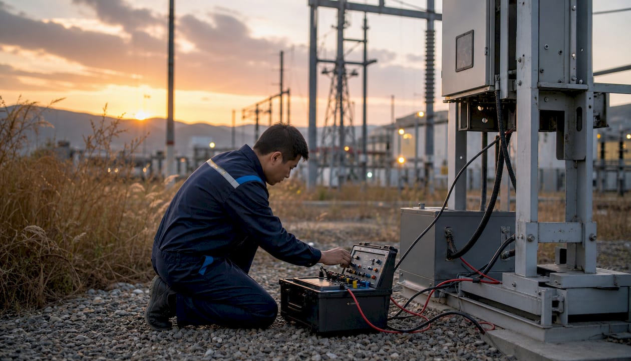
Static testing evaluates individual device settings and accuracy in isolation. A technician applies test signals to a relay and confirms it operates within its specified pickup and timing tolerances. Static testing is fast, repeatable, and well-suited to factory acceptance testing and routine maintenance checks. Its limitation is scope: it confirms that a device works correctly by itself, not that the complete protection scheme works correctly as a system.
Dynamic testing
Dynamic testing evaluates the entire protection scheme under simulated real-world conditions. It applies time-varying signals that replicate actual fault events, including evolving fault currents, voltage collapse, and breaker operation sequences. Dynamic testing evaluates system performance under conditions that static tests cannot replicate, making it the definitive method for verifying scheme-level behavior.
| Attribute | Static testing | Dynamic testing |
|---|---|---|
| Scope | Individual device | Complete protection scheme |
| Test signals | Steady-state | Time-varying, fault-realistic |
| Detects logic errors | Rarely | Yes |
| Standards reference | IEC 60255 | IEC 60255, IEC 61511 |
| Typical use | Factory acceptance, maintenance | Commissioning, scheme validation |
Hardware-in-the-loop (HIL) simulation is the most advanced form of dynamic testing. HIL testing simulates real-time grid behavior, allowing engineers to validate protection logic under complex and dynamic conditions before deployment. This is especially relevant for facilities connected to grids with high renewable penetration, where fault behavior differs significantly from traditional power systems.
Pro Tip:Schedule at least one full dynamic test sequence before final commissioning sign-off. Static test records alone will not satisfy an IEC 61511 audit for a safety instrumented function.
How does functional testing improve reliability and safety?
Functional testing is the practical application of dynamic testing principles to a complete, installed protection scheme. Functional testing gives technicians a comprehensive understanding of how the entire scheme behaves as a unit, not just how individual relays perform.
The reliability benefits are concrete:
- Interoperability verification: Functional tests confirm that overlapping protection zones coordinate correctly. A relay that operates perfectly in isolation may still cause a misoperation if its timing conflicts with an adjacent zone.
- Wiring and logic error detection: Static testing cannot catch a crossed CT secondary wire or a logic rung that fires under the wrong condition. Functional testing under realistic fault scenarios exposes these errors before they cause incidents.
- Commissioning confidence: Technicians who have run a full functional test sequence understand the system’s behavior. That knowledge reduces response time during actual fault events.
- Reduced misoperation risk: Functional testing reduces misoperation risks by verifying that the scheme responds correctly to the specific fault types it is designed to clear.
Functional testing is especially valuable in brownfield projects and system upgrades. Existing wiring may not match as-built drawings. Logic modifications may interact with legacy settings in unexpected ways. Running functional tests after any modification confirms that the upgrade did not introduce new failure modes.
Pro Tip:In upgrade projects, treat the modified system as a new installation for functional testing purposes. Do not assume that previously passing tests remain valid after any change to wiring, settings, or logic.
What practical steps can safety officers take to implement effective verification?
Effective protection system verification requires a structured plan, not a reactive checklist. These steps reflect current best practice under IEC 61511 and IEC 60255.
Start testing incrementally. Test protection circuits as they become available, not only at final commissioning. Discovering a wiring error during panel installation costs hours. Discovering it during final commissioning costs days and may delay startup.
Verify all three SIL gates independently. Assign separate engineers or reviewers to each gate: quantitative probability, systematic capability, and architectural fault tolerance. Independent review prevents the common error of treating a strong quantitative result as sufficient evidence for full SIL compliance.
Maintain a living verification record. Every test, every deviation, and every corrective action must be documented with date, engineer signature, and reference to the applicable standard. Auditors treat gaps in documentation as gaps in compliance, regardless of actual system performance.
Apply HIL simulation for complex schemes. For safety functions in facilities with variable generation sources or non-standard fault profiles, real-time simulation methods provide a level of confidence that static and conventional dynamic tests cannot match. Budget for HIL testing during the design phase, not as an afterthought.
Coordinate across engineering and compliance teams. Verification failures often originate in communication gaps between protection engineers, instrumentation teams, and compliance managers. A shared verification plan with assigned owners for each gate and each test phase eliminates ambiguity about who is responsible for what.
Facilities that follow these steps consistently produce verification packages that withstand regulatory scrutiny. Those that treat verification as a final-stage formality routinely face audit findings, rework, and delayed startup approvals.
Key Takeaways
Protection system verification requires passing all three IEC 61511 SIL gates independently, combining static and dynamic testing, and maintaining complete documentation throughout the system life cycle.
| Point | Details |
|---|---|
| Verification vs. validation | Verification confirms specifications are met; validation confirms stakeholder needs are met. Both are required. |
| Three SIL gates | IEC 61511 requires quantitative, systematic capability, and architectural fault tolerance gates to pass independently. |
| Static vs. dynamic testing | Static testing checks individual devices; dynamic testing validates complete scheme behavior under realistic fault conditions. |
| Incremental testing | Testing circuits as they become available catches errors early and prevents costly rework at final commissioning. |
| Documentation is compliance | Incomplete verification records constitute a compliance failure regardless of actual system performance. |
Indelec’s perspective on verification as a knowledge-building practice
The most persistent problem I see in protection system verification is the reduction of a complex engineering activity to a numeric pass/fail report. Compliance managers focus on PFDavg, print the number, and file it. Relying solely on quantitative reports while ignoring architectural constraints and systematic capability is the fastest route to an audit failure, even when the numbers look good.
Verification is fundamentally a knowledge-building activity. The documentation, the test sequences, the deviation records: these are not bureaucratic overhead. They are the accumulated understanding of how a specific system behaves in a specific facility. That understanding is what allows a protection engineer to respond correctly when an unusual fault event occurs at 2:00 AM.
The shift toward renewable-heavy grids is making this even more critical. Fault behavior in low-inertia systems does not match the assumptions built into legacy relay settings. Static testing against those settings produces a false sense of security. Dynamic simulation under realistic grid conditions is no longer a premium option. It is the baseline for any facility that takes verification seriously.
At Indelec, we have seen facilities with decades of operational history discover fundamental scheme coordination errors during their first properly conducted functional test. That is not a failure of the engineers involved. It is a failure of a verification culture that treated testing as a formality rather than a discipline. The facilities that get this right treat every verification cycle as an opportunity to deepen their understanding of the system, not just to generate a compliance record.
— Indelec
How Indelec supports protection system verification
Indelec has specialized in electrical protection since 1955, combining product engineering with field-tested compliance expertise for industrial facilities worldwide.

The Prevectron3 air terminal with OptiMax patented technology is designed to meet the verification and documentation requirements that safety officers face under current standards. Each installation is supported by certification documentation aligned with applicable lightning protection standards, giving compliance managers the audit-ready evidence they need. Indelec’s technical team also supports protection system assessment and testing coordination for industrial facilities across the full compliance life cycle. Contact Indelec to discuss verification requirements for your facility.
FAQ
What does protection system verification mean?
Protection system verification is the process of confirming that every component of a safety protection system meets its documented specifications. It is an ongoing activity throughout design, installation, and commissioning, not a single end-of-project test.
What is the difference between verification and validation?
Verification confirms that system elements meet their specifications. Validation confirms that the completed system meets top-level stakeholder needs. Both are required under IEC 61511 for safety instrumented systems.
How many gates does SIL verification require under IEC 61511?
IEC 61511 requires three independent gates: quantitative probability of failure, systematic capability of devices, and architectural hardware fault tolerance. All three must pass independently to demonstrate full SIL compliance.
Why is functional testing important in protection system assessment?
Functional testing verifies how the complete protection scheme behaves under realistic fault conditions, detecting wiring errors, logic conflicts, and coordination failures that static device-level tests cannot identify.
When should protection system testing begin on a new installation?
Testing should begin incrementally as circuits become available during installation. Waiting until final commissioning to begin testing significantly increases the risk of discovering errors that require costly rework and cause project delays.