Prepare Facility Teams for ESE Testing: NF C 17102 Checklist
ESE (PDA) air terminals must be verified against NF C 17102 procedures: measure ΔT and record a compliant verification report. The normative checks include ΔT triggering advance and, for product qualification, a laboratory current test. If you lack laboratory proof for your installed terminal, schedule an on-site verification with a competent provider or work through the field checklist below.
TL;DR:
- Laboratory tests confirm the terminal’s triggering performance with ΔT between 10 and 60 microseconds and a 100 kA current test, required before marketing as an ESE.
- On-site verification checks installation integrity, bonding, continuity, and grounding, but does not assess the device’s intrinsic triggering performance.
- Compatibility of field ΔT readings with lab certification depends on environmental conditions, and borderline results should be documented and retested at the lab if needed.
- Maintaining accurate records of tests, calibration, and inspections in the verification report and dossier d’exécution is essential for legal compliance and audit readiness.
- Engaging a qualified organization with accredited laboratory experience ensures proper testing, documentation, and ongoing system verification.
Table of Contents
- Which standards and regulations govern ESE testing
- Laboratory testing versus on-site verification: when each applies
- Field checklist for an on-site ESE verification
- How to read ΔT and other test results
- Reporting, records, and legal responsibilities after testing
- When to bring in a competent organization
- What matters most in the field
- Get your ESE system verified by Indelec
- Standards and reports worth consulting directly
- Sources
- FAQ
Which standards and regulations govern ESE testing
NF C 17102 is the reference document for PDA (paratonnerre à dispositif d’amorçage) systems. Its Annex C sets out the test procedures specific to early streamer emission terminals, and the standard’s other chapters define the dossier d’exécution, the order in which verifications must happen, and what a verification report must contain. Verifications are sequenced: initial (vérification initiale), visual (vérification visuelle), and complete (vérification complète), each with its own scope.
Regulatory obligations sit alongside the technical standard. For installations covered by the classified facilities regime, the Arrêté du 15 janvier 2008 requires that a technical study follow the lightning risk analysis, produced by a competent organization, defining protection measures, placement, and how verification and maintenance will be carried out. The operator must also keep a maintenance notice and a carnet de bord.
- NF C 17102 Annex C defines the PDA/ESE test procedure and acceptance criteria.
- The Arrêté ties the technical study to a documented maintenance and verification plan.
- IEC 62305-3 and the IEC 62561 series are the international references cited alongside NF C 17102 for component and system performance.
ΔT normative range: 10 to 60 microseconds, per INERIS’s assessment, the band that laboratory testing must confirm before a terminal can be marketed as ESE.
Laboratory testing versus on-site verification: when each applies
Laboratory testing and on-site verification answer different questions, and confusing the two is a common source of compliance gaps.
- Laboratory ΔT and current tests qualify the product itself: a lab measures the early triggering advance and, per the INERIS assessment, subjects the terminal to a 100 kA current test and environmental stress checks before the device can be marketed as ESE.
- On-site (in-situ) verification checks the installed system: mounting, bonding, continuity, and general condition, not the terminal’s intrinsic triggering performance.
- Natural lightning observation relies on long-term monitoring of an installed terminal exposed to real strikes, which is slow and depends on local strike frequency.
- Triggered lightning campaigns, run under controlled field protocols, generate strikes on demand but require specialized rocket-triggering infrastructure and are not a routine option for facility teams.
For most facility managers, the practical path is straightforward: rely on the manufacturer’s laboratory certification for the terminal’s ΔT performance, then use periodic on-site verification to confirm the installation still matches the dossier d’exécution. Schedule a full on-site verification at commissioning, at the routine interval set in your maintenance plan, and again after any lightning strike or structural modification near the air terminal.
Field checklist for an on-site ESE verification
A structured sequence keeps an on-site verification consistent with NF C 17102 and defensible if the report is later challenged.
- Review documents before the visit: the technical study, the dossier d’exécution, prior verification reports, and the bill of materials for the installed terminal and conductors.
- Inspect mounting and structural condition: check the mast, fixings, and cage maillée for corrosion, loosening, or physical damage.
- Check bonding and separation distances: confirm equipotential bonding at each junction and that separation distances from other conductive elements match the study.
- Verify continuity: test the down conductor path from the air terminal to the grounding system for electrical continuity.
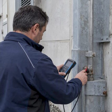
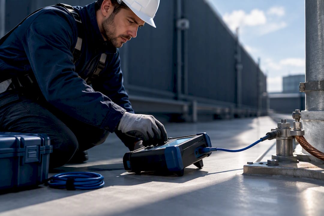
- Connect test instruments: attach the tester per its calibration procedure and, where site equipment allows, capture functional readings relevant to triggering behavior; note that portable functional testers confirm the device is operating, not its lab-certified ΔT value.
- Confirm earthing values: measure ground resistance and compare against the design figures in the technical study.
- Apply safety measures: lockout procedures, fall protection for elevated work, and confirmation that the earthing system is safe to approach before touching test points.
- Record everything: measurements, instrument calibration references, photographs of connections and corrosion points, and signatures of the technician and witness.
Pro Tip:Photograph the tester’s calibration sticker alongside each reading. It ties the measurement to a traceable instrument and closes the most common gap auditors flag in verification reports.
How to read ΔT and other test results
ΔT is the time advance by which the terminal’s streamer emission precedes that of a simple rod under identical test conditions. NF C 17102 and the related INERIS assessment set the acceptable band between 10 and 60 microseconds; a value under 10 microseconds means the device does not qualify as ESE.
- A ΔT within the band, measured under lab conditions, supports the manufacturer’s product certification.
- Nearby conductive structures, antennas, or metal stacks can reduce the effective ΔT observed in the field compared to lab reference conditions.
- A borderline or inconsistent field reading is not, by itself, grounds to condemn the terminal: it usually means environmental interference should be documented and the reading repeated.
One acceptance range governs the check: ΔT between 10 and 60 microseconds, per INERIS, the figure your report should reference whenever ΔT is cited. When results sit near the edges of that band or contradict earlier lab certification, note the surrounding conditions in the report and request a laboratory retest rather than reworking the field data.
Reporting, records, and legal responsibilities after testing
A verification is only as good as its paper trail. The report and the dossier d’exécution together need to show what was tested, against what reference, and by whom.
- A compliant verification report states the reference standard, test method, instrument calibration, measured values, and a clear conclusion against the acceptance criteria.
- The dossier d’exécution should include the original technical study, as-built drawings, and every prior verification report in sequence.
- The carnet de bord, kept by the operator under the Arrêté du 15 janvier 2008, logs maintenance actions, inspections, and any incident affecting the protection system.
- Extra verification is triggered by a documented lightning strike, a structural modification near the terminal, or damage discovered during routine inspection.
Verification frequency follows the interval set in the technical study, typically annual or biannual depending on the site’s risk level, and the carnet de bord should show that interval was respected.
When to bring in a competent organization
Not every facility team has the instruments or the standing to sign off a compliant report. Before commissioning a verification, ask for evidence of laboratory accreditation behind the terminal’s certification, documented experience with NF C 17102 procedures, and a sample report template that matches the structure described above.
A standard verification contract typically covers the risk analysis and technical study (ARF/ET), an on-site installation check, functional testing, a written report, and a maintenance plan going forward, the same scope Indelec’s lightning protection services are structured around. The company has significant experience in lightning protection, operates a dedicated R&D center, and serves industrial, commercial, and infrastructure sectors internationally.

What matters most in the field
Traceability beats elegance in this work: a measurement nobody can reproduce is worth less than a modest one with a calibration record attached. The recurring field failures are mundane: bonding joints left loose after other trades finish, corrosion hidden behind a cable gland, and modifications to the roof or mast that never made it into the dossier d’exécution. Keep the paperwork current and the bonding tight, and most compliance disputes never happen.
— INDELEC
Get your ESE system verified by Indelec
Testing an ESE terminal correctly means combining lab-grade standards knowledge with a technician who has actually connected the instruments before. Indelec’s lightning protection team runs the full sequence: risk analysis and technical study (ARF/ET), installation, verification and maintenance, and dossier preparation, so your carnet de bord and reports stay audit-ready without you chasing the paperwork yourself.

- Risk analysis and technical study (ARF/ET) to define your protection requirements.
- On-site verification and maintenance contracts to keep terminals within their acceptance criteria.
- Dossier d’exécution preparation and report templates aligned with NF C 17102.
Reach out through Indelec’s services page to request a quote or schedule a verification visit.
Standards and reports worth consulting directly
- NF C 17102 (AFNOR) for the prescriptive PDA/ESE test procedures in Annex C.
- The INERIS assessment for ΔT measurement practice and laboratory current test detail.
- The Arrêté du 15 janvier 2008 for the legal basis behind the technical study and maintenance notice.
Field clamps and connection hardware for taking these measurements safely, such as the Adesatos heavy-duty grounding clamp, are worth having in the test kit alongside a calibrated tester.
Sources
- Protection contre la foudre – Systèmes de protection contre la foudre à dispositif d’amorçage – NF C 17102
- Arrêté du 15 janvier 2008 relatif à la protection contre la foudre de certaines installations classées — Article 3
- Prestations
FAQ
How do you test a lightning rod?
Testing combines a visual inspection of mounting, bonding, and corrosion with electrical continuity checks and, where applicable, ΔT measurement referenced against NF C 17102. Results, instrument calibration data, and photographs are recorded in a written verification report kept with the dossier d’exécution.
Is a lightning risk study legally required?
Yes, for installations covered by the classified facilities regime: the Arrêté du 15 janvier 2008 requires a technical study following the risk analysis, produced by a competent organization, along with a maintenance notice kept by the operator.
How can I test my surge protection device?
Surge protective devices are checked through visual inspection of their status indicators and periodic functional testing per their manufacturer’s maintenance schedule, generally aligned with the same verification cycle as the lightning protection system. A qualified technician should confirm the device still meets its rated protection level during the same visit as the ESE verification.
What is the standard for lightning rods?
NF C 17102 governs early streamer emission (PDA/ESE) systems specifically, while IEC 62305-3 and the IEC 62561 component series apply more broadly to lightning protection system design and hardware performance.