Advances in Grounding Technology: 2026 Engineer’s Guide

TL;DR:
- Advances in grounding technology now emphasize multi-frequency impedance testing, enhanced earth electrode materials, and integrated bonding for lightning and equipment grounds. IEEE Std 81-2026 establishes new standards requiring variable frequency injection up to 50 A, digital filtering, and safety features like galvanic isolation, improving accuracy and safety in complex soil and industrial environments. Combining deep borehole electrodes with conductive backfill and unified bonding practices significantly enhances grounding performance and surge protection in challenging conditions.
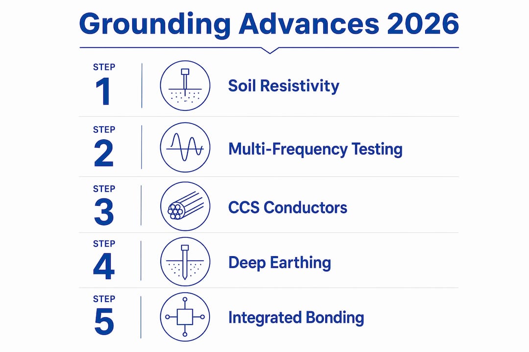
Advances in grounding technology are defined by three converging developments: multi-frequency impedance testing, improved earth electrode materials, and integrated bonding of lightning protection with equipment grounding systems. The publication of IEEE Std 81-2026 marks a turning point for how engineers measure, design, and verify grounding systems in industrial and commercial facilities. These changes are not incremental. They address long-standing accuracy gaps in soil testing, introduce new conductor materials into mainstream design software, and tighten the requirements for step and touch voltage analysis. If your facility’s grounding practices still rely on single-frequency DC testing or disconnected lightning and equipment grounds, your compliance posture is already behind.
What are the latest IEEE 81-2026 grounding testing standards?
IEEE Std 81-2026 defines multi-frequency current injection as the new baseline for grounding impedance measurement, replacing the single-frequency and DC methods that dominated field practice for decades. The standard requires testers to apply variable frequencies to overcome soil polarization and environmental interference, with injection currents up to 50 A capable of detecting sub-ohm grid impedance reliably. That level of sensitivity matters most in large substation grids where a 0.1 Ω error in measured resistance can translate to thousands of volts of miscalculated ground potential rise.
How multi-frequency injection works
The standard specifies test frequencies slightly offset from the power system frequency, typically 45 Hz and 55 Hz in a 50 Hz environment. Digital Fourier transform filtering separates the injected test signal from 50/60 Hz grid noise, giving engineers a clean impedance reading even in electrically noisy industrial environments. This technique eliminates the guesswork that plagued older analog testers operating at or near power frequency.
Instrumentation safety requirements
IEEE 81-2026 also mandates specific safety features in the test equipment itself. Modern earth resistance testers must include active insulation monitoring and galvanic isolation to protect operators working on energized or partially energized grounding systems. Residual voltage discharge circuits and continuous loop impedance monitoring are now required, not optional. These features prevent electrocution and equipment damage when a fault condition develops mid-test.
Key capabilities required by IEEE 81-2026 compliant testers:
- Variable frequency injection (not fixed 50/60 Hz) to counter soil polarization
- Injection current capacity up to 50 A for low-impedance grid measurement
- Galvanic isolation between test circuit and operator interface
- Residual voltage discharge before and after each test cycle
- Continuous loop impedance monitoring throughout the test sequence
- Digital signal processing to filter power frequency interference
Pro Tip:Before purchasing a new earth resistance tester, request the manufacturer’s IEEE 81-2026 compliance documentation specifically. Many instruments marketed as “updated” still use single-frequency injection with a software label change. Verify the hardware specifications, not the marketing copy.
How are grounding system designs evolving with new materials?
The integration of copper-clad steel (CCS) conductors into mainstream grounding design software is one of the most practical grounding technology improvements of the past two years. Copperweld Century® and ArcAngel® CCS conductors are now directly modeled within CDEGS and WinIGS, the two dominant grounding analysis platforms used by power engineers worldwide. This integration allows engineers to assess electrical and mechanical performance tradeoffs within a single design workflow rather than switching between disconnected tools.
Copper-clad steel vs. solid copper conductors
| Property | Copper-Clad Steel (CCS) | Solid Copper |
|---|---|---|
| Tensile strength | High (steel core) | Lower |
| Conductivity | ~40% IACS (ArcAngel®) | 100% IACS |
| Corrosion resistance | Good with copper cladding | Excellent |
| Cost | Lower | Higher |
| Theft risk | Reduced | High |
| Software modeling | CDEGS, WinIGS integrated | Standard |
CCS conductors offer a meaningful tradeoff for facilities in high-theft areas or where mechanical durability under soil movement is a priority. The software modeling integration removes the previous workflow inefficiency of manually converting CCS electrical parameters into legacy design tools. Engineers can now run iterative grid designs comparing CCS and solid copper side by side within the same simulation.
Deep earthing with conductive backfill
High-resistivity soils present a persistent challenge for achieving low grounding resistance. Conventional soil treatment with bentonite or salt compounds provides temporary improvement but degrades over time. A more durable solution combines deep borehole electrodes with conductive graphite backfill. In one documented case, a 40 m deep earthing system combined with conductive graphite backfill reduced grounding resistance to 0.28 Ω in gravelly soil where conventional methods had stalled above 2.5 Ω. That result demonstrates what is achievable when deep installation and backfill chemistry work together.
Extremely low grounding resistance in difficult soils requires combining deep electrode installation with conductive backfill, not one or the other. Facilities on rocky terrain, sandy coastal sites, or permafrost zones should treat this approach as the primary design strategy rather than a last resort.
Pro Tip:Conduct a detailed soil resistivity profile using a Wenner four-electrode survey before specifying electrode depth. Resistivity can vary by an order of magnitude between the surface and 30 m depth. Designing to the surface reading alone will produce an undersized grounding system.
What are the advances in step and touch potential analysis?
Step and touch potentials are the voltages a person can experience during a ground fault. Step potential is the voltage between two feet separated by one meter on the soil surface. Touch potential is the voltage between a hand contacting energized metalwork and the feet. Both are governed by IEEE 80-2013 and the forthcoming 2026 revision, and both depend directly on the accuracy of the grounding resistance measurement.
The most significant advance in this area is the shift from using maximum available fault current to using the actual grid current limited by protective devices. In low-resistance grounding (LRG) schemes, the fault current Ig is typically 100 A, not the tens of kiloamperes available upstream. Ground potential rise (GPR) equals Ig multiplied by Rg. Using 100 A instead of 10,000 A reduces the calculated GPR by a factor of 100, which changes the entire safety mitigation strategy for a facility.
Practical steps for step and touch voltage verification
- Conduct a fall-of-potential survey with potential electrode readings at 20%, 40%, 60%, and 80% of the distance between current electrodes. This identifies the true resistance minimum and flags any buried metalwork distorting the measurement.
- Document the actual protective device settings that limit fault current to the earth grid. Do not default to the maximum available fault current from the utility.
- Calculate GPR using the verified Ig value. Compare against IEEE 80 tolerable touch and step voltage limits for the specific body weight and fault clearing time of your system.
- Verify that surface layer treatment (crushed rock, asphalt) is intact and meets the resistivity assumptions in your calculation. Degraded surface layers invalidate the safety margin.
- Re-test after any significant grid modification, soil disturbance, or change in protective device settings.
| Calculation input | Conservative (incorrect) approach | Accurate approach |
|---|---|---|
| Fault current used | Maximum upstream fault current | Actual Ig limited by protective device |
| GPR result | Overestimated by 10x to 100x | Realistic hazard voltage |
| Mitigation cost | Unnecessarily high | Proportionate to actual risk |
| Safety margin | Appears larger than reality | Verified and defensible |
Assuming full fault current in LRG systems leads to overestimated GPR and expensive mitigation that does not reflect actual risk. Using the correct Ig value produces a defensible safety analysis that satisfies both IEEE 80 and insurance requirements.
How do modern bonding practices integrate grounding and lightning protection?
Integrated bonding is the practice of connecting all grounding electrode systems in a building, including lightning protection, power system ground, and communication cable shields, to a single common bonding point. IEC 62305-3 and NFPA 780-2014 both mandate this approach, and the reason is straightforward. When lightning current enters a structure through a separate lightning protection ground that is not bonded to the equipment ground, the potential difference between the two systems drives surge current through sensitive equipment. The equipment becomes the conductor between two ground references at different potentials.
Single-point bonding eliminates this potential difference at the source. All grounds reference the same equipotential plane, so lightning current distributes across the combined electrode system rather than through equipment enclosures and cable shields.
Practical bonding requirements under current standards:
- All lightning protection down conductors must connect to the main equipotential bonding bar
- Power system neutral and equipment grounding conductors bond at the same bar
- Communication cable shields, data network grounds, and antenna grounds connect at the same point
- Conductor sizing for bonding connections follows IEC 62305-4 minimums, typically 16 mm² copper for internal bonding conductors
- Bonding connections require periodic inspection and resistance testing to verify continuity
For facilities with existing separate lightning and equipment grounds, the industrial lightning protection guide provides a practical framework for retrofitting bonding connections without taking systems offline.
Pro Tip:When retrofitting bonding on an existing facility, use a clamp-on current meter to measure circulating currents between separate ground systems before bonding them together. High circulating currents indicate a power quality problem that bonding alone will not fix and may make worse.
Key takeaways
Modern grounding safety depends on accurate measurement, correct fault current assumptions, and fully integrated bonding across all electrode systems.
| Point | Details |
|---|---|
| IEEE 81-2026 testing standard | Multi-frequency injection up to 50 A with galvanic isolation is now the compliance baseline for grounding impedance measurement. |
| CCS conductor modeling | Copperweld Century® and ArcAngel® conductors in CDEGS and WinIGS allow direct electrical and mechanical tradeoff analysis in design. |
| Deep earthing with backfill | A 40 m electrode with graphite backfill achieved 0.28 Ω in gravelly soil where conventional methods could not reach below 2.5 Ω. |
| Correct fault current in LRG | Using actual Ig (e.g., 100 A) instead of maximum fault current produces realistic GPR and avoids over-engineered mitigation. |
| Single-point bonding | IEC 62305-3 and NFPA 780-2014 require all grounds to bond at one point to prevent surge current from routing through equipment. |
What Indelec has learned from decades of grounding work
The most common mistake we see in the field is not a wrong calculation. It is the wrong starting assumption. Engineers inherit a grounding system, assume it was designed to current standards, and run their safety analysis on top of that assumption. When the underlying measurement is wrong, every calculation built on it is wrong too.
Multi-frequency testing per IEEE 81-2026 is not just a regulatory checkbox. It is the only way to get a trustworthy impedance number on a complex grid in real soil conditions. We have seen single-frequency measurements underreport grid impedance by 30% or more in high-clay soils where polarization effects are significant. That error propagates directly into the GPR calculation and the touch voltage result.
On the design side, the shift to CCS conductors modeled in CDEGS and WinIGS has changed what is practical to specify. Engineers who previously avoided CCS because of modeling uncertainty now have no reason to default to solid copper in every application. The tradeoff analysis is built into the workflow.
Deep earthing with conductive backfill remains underutilized. Facilities on difficult soils often accept a grounding resistance of 5 Ω or higher because conventional methods cannot do better. The research is clear: combining a deep borehole with graphite backfill can reach below 0.5 Ω in soils where surface electrodes fail. That is not a niche technique. It is the correct technique for the soil condition.
Bonding is where lightning protection and grounding engineering must work as one discipline. Separate grounds are not a conservative approach. They are a liability. Every facility we assess with disconnected lightning and equipment grounds has measurable potential differences between them. Those differences become surge paths during a strike.
— Indelec
Explore Indelec’s grounding and lightning protection solutions

Indelec has delivered grounding and lightning protection systems across industrial, energy, and infrastructure sectors since 1955. For facilities in challenging soil conditions, Indelec’s deep earth grounding drilling service combines borehole installation with conductive backfill to achieve verified low-resistance grounding where conventional electrodes cannot. For integrated lightning protection design aligned with IEC 62305-3 and NFPA 780-2014, Indelec’s lightning protection system application team provides engineering support from site survey through compliance certification. Contact Indelec to discuss a grounding assessment or system upgrade tailored to your facility’s soil conditions, fault current profile, and applicable standards.
FAQ
What does IEEE 81-2026 require for grounding tests?
IEEE 81-2026 requires multi-frequency current injection up to 50 A, digital signal filtering to remove power frequency noise, and instrumentation with galvanic isolation and residual voltage discharge circuits. Single-frequency and DC testing methods no longer meet the standard for complex grounding grid measurement.
Why is grounding important in industrial electrical systems?
Grounding limits the voltage rise on equipment enclosures and structures during a fault, protecting personnel from step and touch voltages and providing a low-impedance return path for fault current to operate protective devices. Without a verified low-resistance ground, fault clearing times increase and personnel hazard voltages rise proportionally.
What is the fall-of-potential method for ground resistance testing?
The fall-of-potential method places a current electrode and a potential electrode at measured distances from the ground under test, then records resistance at multiple electrode spacings (20%, 40%, 60%, 80% of the current electrode distance) to identify the true resistance minimum of the grounding system.
How does deep earthing with conductive backfill improve grounding performance?
Deep borehole electrodes combined with conductive graphite backfill achieve contact with lower-resistivity soil layers and reduce electrode-to-soil contact resistance simultaneously. This combination has produced verified grounding resistance below 0.3 Ω in gravelly soils where surface electrode arrays could not reach below 2.5 Ω.
What is single-point bonding and why does it matter for lightning protection?
Single-point bonding connects all grounding electrode systems, including lightning protection, power, and communications grounds, to one common equipotential bar. This eliminates the potential difference between separate grounds that would otherwise drive lightning surge current through sensitive equipment during a strike.