Lightning Protection Design: A Step-by-Step Guide for French Sites
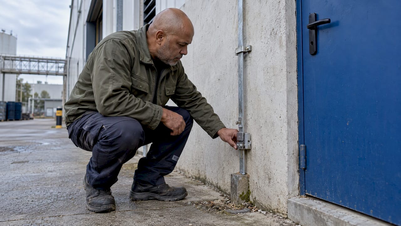
A sound lightning protection design starts with a risk analysis, not with a rod on the roof. You assess the structure and its surroundings, set a protection level, then lay out the external system (air terminals, down conductors, earthing) and coordinate it with internal protection (equipotential bonding and surge protective devices). In France that work is framed by the NF EN 62305 series and, when early streamer emission air terminals are used, by NF C 17-102. This guide walks through each step in the order a design team follows.
TL;DR
- Design begins with a lightning risk analysis (ARF) that decides whether protection is needed and at what level, then a technical study (ET) turns that into a drawn system.
- A complete system has three external parts, capture, down conductors and earthing, plus internal protection: equipotential bonding and surge protective devices.
- For classified installations (ICPE), French regulation requires the analysis, study, installation and verification to be done by recognized competent bodies and persons.
- Design is not finished at handover: the execution file, periodic verification and the logbook keep the system defensible.
- Plan it early. Options such as using façade reinforcement as part of a mesh cage only work if they are decided at the construction stage.
Table of Contents
- What lightning protection design actually covers
- The French framework: which standards apply
- Step 1: Run the lightning risk analysis
- Step 2: Set the protection level and choose the approach
- Step 3: Lay out air terminals, down conductors and earthing
- Step 4: Coordinate with bonding and surge protection
- Step 5: Document, verify and maintain
- A practical design workflow
- Our perspective on design
- From design to a signed scope
- FAQ
- Sources
What lightning protection design actually covers
Lightning protection design is the engineering process that decides what to install, where, to what rating, and how it ties into the rest of the building. It is not a catalog selection. The same roof can need very different solutions depending on what is under it.
The hazards are defined in the standards. IEC 62305-2:2024 describes how flashes to earth can damage a structure and its contents, cause failure of electrical and electronic systems, and injure people or animals in or near the structure. The consequences can also reach the surroundings or the environment, and the availability of the structure and its internal systems can suffer if damage is frequent.
Two families of effects follow from that. Direct effects are physical damage: fire, mechanical destruction, a strike on the roof or a mast. Secondary effects are overvoltages and surges that enter through power, data and telecom lines and damage equipment, even when the building itself is not hit. A design that handles only one family leaves the other open, which is why a lightning protection system is described as three interdependent external components (capture, down conductors, earthing) working with internal protection.

The French framework: which standards apply
Four documents come up in nearly every French project.
| Document | What it covers | When it matters |
|---|---|---|
| NF EN IEC 62305-1 | General principles: lightning current parameters, damage, need for protection, protection measures | Every project, as the base of the series |
| NF EN 62305-2 | Risk assessment | To decide whether protection is needed and at which level |
| NF EN 62305-3 and -4 | Physical damage to structures; electrical and electronic systems | To design the external and internal systems |
| NF C 17-102 | Systems with early streamer emission air terminals (ESEAT) | When an ESE rod is part of the design |
The AFNOR Norm’Info page confirms the scope of Part 1: current parameters, damage due to lightning, the necessity of protection, protection measures and the basic criterion for protecting structures. The AFNOR page for NF C 17-102 (September 2011 edition) lists design, down conductors, equipotential bonding, separation distance, earth terminations, special measures for antennas and explosive storage zones, and a section on the execution file, verification and maintenance.
For industrial sites, the regulatory layer matters as much as the standards. According to the INERIS Omega-3 report, the current text for ICPE is the arrêté of 4 October 2010 as modified by the arrêté of 19 July 2011. It requires the risk analysis, the technical study, the installation of protections and their verification to be carried out by recognized competent bodies and persons. INERIS also notes that this moved French practice from treating structure protection separately to a global approach, which adds parameters and makes the analysis more complex. In practice, that is a reason to bring in a specialist before the layout is drawn. You can find our overview of the standards on our lightning standards page.
Step 1: Run the lightning risk analysis
The analysis answers three questions: is protection required, what kind, and to what level. Skipping it is the most common way to end up with a system that is either oversized or insufficient. Our lightning risk assessment guide goes deeper on the method.
What data the analysis needs
According to the Actu Électricité article, an analysis under NF EN 62305-2 takes into account structural characteristics, use, occupancy, geographical location and the consequences of a strike. The Legrand/Sonepar documentation breaks the inputs down further:
- Building dimensions and construction type.
- Type and number of lines entering the building.
- Environment and local lightning density.
- Number of people present.
- Sources of damage: S1 (strikes on the building), S2 (near the building), S3 (on lines), S4 (near lines).
- Types of loss: L1 (human life), L2 (public services), L3 (cultural heritage), L4 (economic).
- The acceptable risk for that type of building and use.
Gather these before the first meeting: site plans, a list of incoming services, the occupancy profile, and what the process or equipment inside is worth in downtime.
Using the right flash density
For ICPE, the INERIS Qualifoudre FAQ (version 3, November 2023) states that the local flash density Nsg supplied by Météorage for the commune must be used in the R1 calculation without dividing it by 2. The same document notes that NF EN 62305-2 introduces protection levels above level I, which may be needed for external and internal protection. A small input choice changes the result, so it should be documented in the study.
Energy and other specialist structures
Some structures carry particular exposure, for example solar plants with long cable runs across open ground. For a view of how risk analysis and protection level selection apply to photovoltaic installations, see this page on lightning protection for photovoltaic plants. The same logic applies in France: the analysis decides, not habit.
Note also that the decision to protect does not always depend on the calculated risk. IEC 62305-2:2024 says protection can be chosen regardless of the result where the owner wants no avoidable damage. For a data hall or a high-value production line, that is often the right call.
Step 2: Set the protection level and choose the approach
The analysis outcome sets a protection level, from I (most demanding) to IV. That level drives dimensions: for a mesh cage, the Cahiers Techniques du Bâtiment article states that the four levels set mesh spacing from 5 to 20 m per side.
Then comes the choice of capture approach. The common options are:
- Rod-based capture, either simple rods or ESE rods designed to NF C 17-102. Suited to a wide range of roofs and open areas.
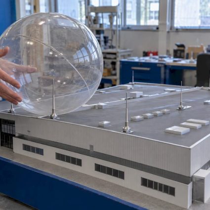
- Mesh cage, several short capture points (30 to 50 cm rods) joined by a metal mesh on the roof and façade. The same article describes it as little used in France and mainly reserved for sensitive sites such as Seveso sites, large logistics buildings and IGH.
- Combinations, for example a mesh on a main roof and a mast near a tank or antenna.
The decision depends on roof geometry, the equipment on it, access for maintenance, and whether the building is new. We cover our own range for each approach under lightning rods and in the lightning protection system application page.
Step 3: Lay out air terminals, down conductors and earthing
This is the part drawings show, and where details matter. The values below come from practice described for ESE-based systems and from NF C 17-102. Always confirm them against the study for your site and the edition in force.
Air terminals
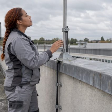
The Actu Électricité article gives the tip of the rod at least 2 m above the protected area. The NF C 17-102 verification checklist, in the English text of the standard, also checks that the ESEAT is 2 m or more above any object in the protected zone. Mast height, mast fixing and wind loads are part of the structural coordination with the architect or engineer. Our mast range and mast mounting stands are designed with that in mind.
Down conductors
A practical set of rules from the same article:
- Each rod connects to two down conductors on two different façades.
- Tinned copper conductors of at least 50 mm², fixed at three points per metre.
- A path as straight as possible, with a bend radius of at least 20 cm.
- More than 3 m from gas columns.
- Protected over 2 m at ground level by a rigid sleeve, with a disconnection terminal.
- Two down conductors for a single rod when the path exceeds 35 m.
NF C 17-102, per the English text, places down conductors preferably on the outside of the structure. On a combustible wall, when the conductor is not copper, you need either a separation of at least 0.10 m or a section of at least 100 mm². Two conductors count as independent only if they do not run in parallel, meaning more than 2 m apart along a straight line. See our down conductors and clamps and fixings.
Earth termination
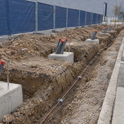
The target is an earth resistance of 10 ohms or less. Per the Actu Électricité article, if that cannot be reached, the fallback is at least 100 m of buried electrode. Each down conductor gets its own earth termination, and the standard also lists a foundation earth electrode, equipotential bonding bars and disconnectable bonding devices among the system components. Where soil is poor or space is limited, deep earth drilling is one solution to study. Our earthing range covers the standard components, and the grounding maintenance guide explains how to keep values stable over time.
Using the building itself
The Cahiers Techniques du Bâtiment article notes that a mesh cage can use the reinforcement of a concrete façade to carry lightning currents to ground, provided it is planned from the construction stage. Continuity of the rebar ensures equipotentiality, and spot welding is needed where connections are bolted. This is the clearest argument for involving the lightning designer at the permit and structural design stage, not after the shell is up.
Step 4: Coordinate with bonding and surge protection
External protection handles the strike. Internal protection handles what the strike sends along cables and metalwork. The design must coordinate the two, as the Actu Électricité article stresses, and it presents the risk analysis as the way to avoid both costly oversizing and insufficient protection.
For low voltage, the Legrand/Sonepar documentation summarizes NF C 15-100 requirements:
- SPDs are mandatory at the origin of new or renovated installations with an LPS or lightning rod, and for aerially fed installations in AQ2 zones (Nk above 25).
- A Type 1 or Type 1+2 SPD (Iimp of at least 12.5 kA) is mandatory at the origin of an installation with a lightning rod.
- For buildings above 10 m, a Type 2 SPD is recommended for private parts and floor panels.
- Protection level I corresponds to a 200 kA lightning current on the LPS and an SPD Iimp of 25 kA per pole.
The same IEC 62305-2:2024 text points to IEC 60364-4-44, which always requires an SPD at the power entrance when overvoltage consequences affect human life, public services, cultural heritage, or commercial or industrial activity. Telecom and data lines need the same thinking. Our surge protection devices and surge protection installation guide cover selection and placement, and our low voltage surge protection cabinets suit larger distribution boards.
Step 5: Document, verify and maintain
A design that cannot be proven does not hold up at inspection. For ICPE, the INERIS Omega-3 report says the operator must be able to present the ARF, the technical study, the verification and maintenance notice, verification reports and the logbook (carnet de bord). The ARF and the study may be two parts of one document.
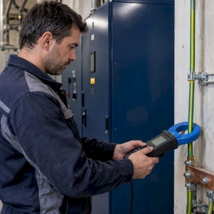
For NF C 17-102 systems, the English text of the standard sets the verification rhythm: after installation, periodically on a schedule, and whenever the structure is modified, repaired or struck. The initial check covers the 2 m height rule, the number of down conductors, conformity of components to the standard and to the NF EN 50164 and NF EN 61643 series, routing and continuity, and fixings. Faults found should be corrected as soon as possible.
The execution file the contractor produces at handover should include:
- The required protection level and its justification.
- ESEAT type and characteristics, and the test procedure.
- Number and location of down conductors.
- Whether a lightning event counter is installed, and where.
- Justification of electrical insulation and of equipotential bonding, including SPDs.
- Type and value of the earth terminations.
A lightning strike counter gives maintenance teams a record of events, which helps decide when an extra inspection is due.
A practical design workflow
- Brief. Collect plans, services entering the site, occupancy and process criticality.
- Risk analysis (ARF). Use local flash density and document each input.
- Technical study (ET). Fix the protection level, capture method, conductor routes, earthing and SPD scheme.
- Coordination. Check roof loads, façade finishes, cable routes and other trades with the architect and engineers.
- Installation. Follow the study and keep photos of buried work before backfilling.
- Verification and file. Test, correct, then archive the execution file and open the logbook.
- Maintenance plan. Schedule periodic checks and post-strike inspections.
Our own view of that sequence is laid out in the facility lightning safety workflow.
Our perspective on design
We have been working on lightning protection since 1955, and the pattern we see most is that the best systems are decided early and documented well.
The risk analysis is where value is created. It lets you protect what actually needs protecting, at the level it needs, so the budget goes to the right places. That is why we offer the analysis and technical study as the first step, then installation, verification and maintenance under one roof.
We also treat external and internal protection as one design. A rod and down conductors without a coordinated earthing and surge protection scheme leave half the problem open. Our range covers rods, masts, down conductors, earthing and surge protection, and our R&D center works on solutions that follow changing standards and climate conditions.
Finally, we encourage owners and architects to call us at the concept stage. Routing conductors, sizing masts and using structural elements are far easier before the building is closed.
INDELEC
From design to a signed scope
If you own, manage or build a site and need a lightning protection design, we handle the risk analysis and technical study, supply the hardware, install it, then verify and maintain it. Start from our lightning protection services, which cover each stage described above.

Send us your plans and the list of services entering the site, and we will propose the scope. You can also browse the full list of services or the surge protection and earthing ranges.
FAQ
Do I need a lightning protection design for every building?
Not automatically. The risk analysis under NF EN 62305-2 decides whether protection is needed and at what level. For ICPE, French regulation makes the analysis and technical study mandatory, carried out by recognized competent bodies. An owner can also choose to protect regardless of the calculated result.
What is the difference between the ARF and the technical study?
The ARF (lightning risk analysis) establishes whether protection is needed and what level is required. The technical study (ET) defines the system that delivers that level: capture, conductors, earthing and surge protection. They can be two parts of the same document.
What earth resistance should I design for?
The practical target for ESE-based systems is 10 ohms or less. If it cannot be reached, a minimum of 100 m of buried electrode is the described fallback. Your study should state the exact requirement for the standard and edition applied.
Are surge protective devices part of the design?
Yes. Under NF C 15-100, an SPD is mandatory at the origin of new or renovated installations with a lightning rod or LPS, with a Type 1 or Type 1+2 device of at least 12.5 kA Iimp. Internal protection is coordinated with the external system in the same study.
How often must a lightning protection system be checked?
NF C 17-102 calls for verification after installation, periodically on a schedule, and after any modification, repair or strike. For ICPE, the verification reports and logbook must be available to the inspector. The schedule is set in your verification and maintenance notice.
Sources
- IEC 62305-2:2024
- Actu Électricité: NF EN 62305 and practical implementation
- AFNOR Norm’Info: NF EN IEC 62305-1
- AFNOR Editions: NF C 17-102
- INERIS Omega-3 report on ICPE lightning protection
- INERIS Qualifoudre FAQ, version 3, November 2023
- Legrand/Sonepar surge protection documentation
- NF C 17-102:2011, English text
- Cahiers Techniques du Bâtiment: Le paratonnerre, protection normalisée contre la foudre
- Lightning protection for photovoltaic plants