Lightning Rod Placement: Where to Put Rods on a Building
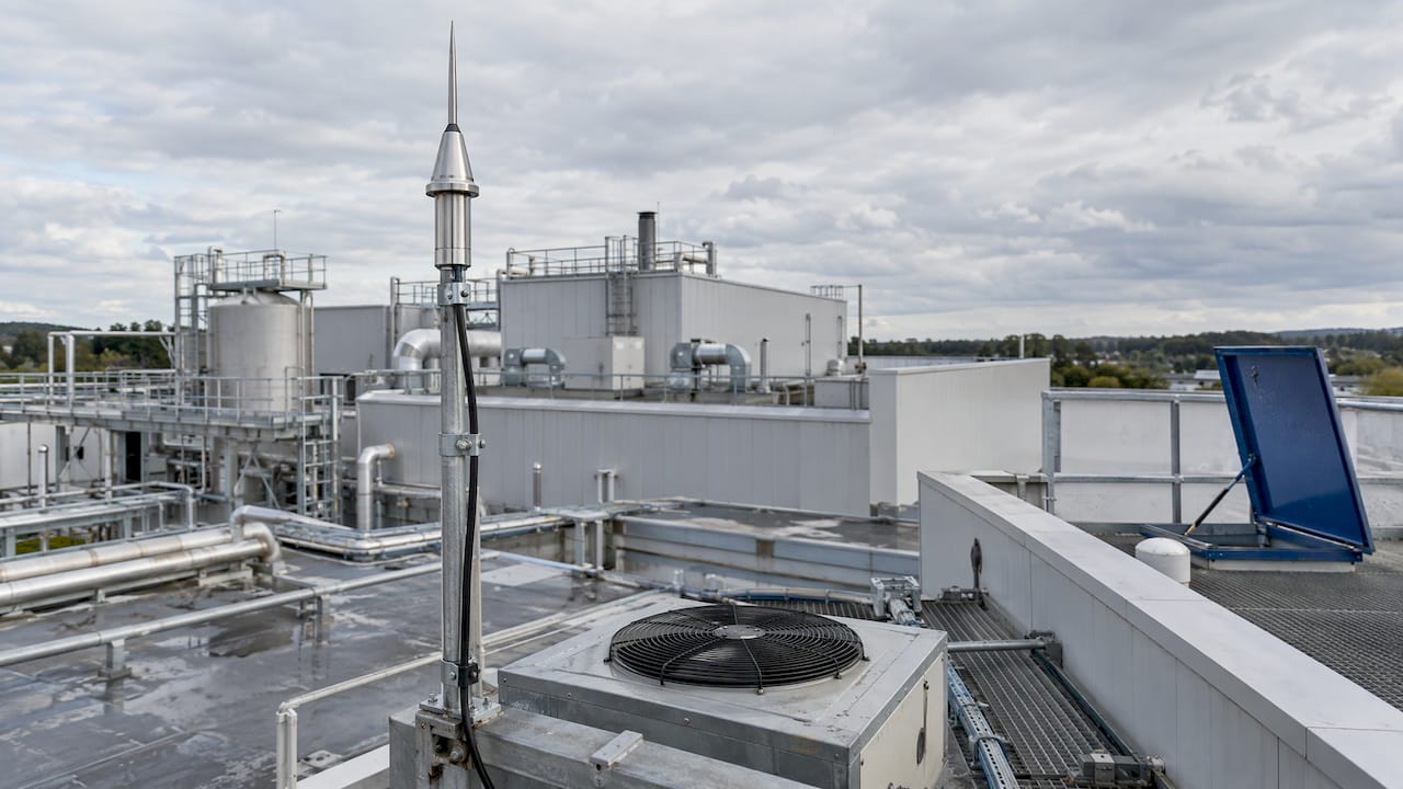
Place a lightning rod at the highest exposed points of the structure, such as ridges, chimneys, towers and roof equipment. Then confirm the position by calculation, not by eye. In France, the position, the tip height and the protected area all follow from a lightning risk analysis and from the design rules of the standard you apply. The usual references are NF C 17-102 for early streamer emission (ESE) terminals and the NF EN IEC 62305 series for conventional systems. This guide walks facility owners, contractors, architects and maintenance teams through that logic, step by step.
TL;DR
- Start with a risk analysis. It sets the protection level, and the level drives every placement decision that follows.
- Prioritize the high and vulnerable points: ridges, chimneys, towers, terrace rooms, extractors, photovoltaic arrays and flat-roof equipment.
- For an ESE terminal, NF C 17-102 requires the tip to sit at least 2 m above the area it protects, roof equipment included.
- Plan the down conductors and the earth termination together with the rod, not afterward.
- Verify the system after installation, periodically, after any structural change and after a strike.
Table of Contents
- Start with the risk analysis, not the roof plan
- Where rods go on a roof
- Choosing the height
- How the protected area is defined
- Conventional systems: capture points and meshed cages
- Down conductors and earthing belong in the same plan
- Site survey: neighbors, utilities and special zones
- A worked placement sequence
- Our perspective on placement
- Keeping the placement effective: inspection and maintenance
- Work with us on your next placement study
- FAQ
- Sources
Start with the risk analysis, not the roof plan
Most placement mistakes begin with someone marking the highest point on a drawing and stopping there. The highest point matters, but it is only one input. NF C 17-102 treats the decision to protect a structure as a function of lightning probability, severity and acceptable consequences. Its risk guide lists public buildings, tall structures, facilities holding dangerous materials and structures with vulnerable or valuable equipment as typical candidates.
The 2011 edition of the standard states that protection decisions begin with a risk analysis that establishes the minimum required protection level. Only once that level is known does the design determine where the air terminals go, how the down conductors run and what type of earth termination is needed, and where it is located.
For ERP buildings (public-access premises) in France, the ADEE regulatory guide identifies NF EN 62305-2 as the complete risk-assessment method and FDC 17-108 as the simplified one. It adds that the latest applicable edition should be used. AFNOR lists NF EN IEC 62305-1, general principles as in force, published in October 2024.
In practice, this means the same building can end up with different placements depending on what happens inside it. A warehouse with racking and a plant with sensitive process control will not receive the same level, even if the roofs look alike. If you want to see how the assessment works before you commission one, our lightning risk assessment guide covers the inputs.
Where rods go on a roof
Begin with the prominent and vulnerable features
The research behind NF C 17-102 is clear on what the designer must look at. The standard names towers, weathervanes, sharp objects, chimneys, gutters, edges, ridges, extractors, photovoltaic cells, balustrades, staircases and flat-roof equipment rooms as features to consider in the placement design. A site walk should therefore produce a list, not a single point.
A useful way to sort the list:
- Tallest elements: towers, stacks, mast bases, lift overruns and terrace rooms.
- Edges and ridges: the lines along which a strike is most likely to attach on a pitched or stepped roof.
- Roof equipment: extractors, air handling units, antennas, photovoltaic arrays and anything metallic that is wired into the building.
- Standalone structures: tanks, small sheds, pump houses and canopies that sit outside the main footprint.
Multi-level roofs and stepped buildings
A building with several roof levels cannot be treated as one flat surface. Each level has its own highest points and its own equipment. The designer checks whether a terminal on the top level covers the lower ones at the heights where equipment actually sits. When it does not, additional terminals go on the lower levels. The check is geometric: it uses the protection radius at the relevant height, not a general impression that the rod “covers” the building.

Chimneys, extractors and roof equipment
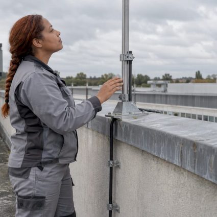
Chimneys and extractors are classic strike points, and they are often the elements people forget when the rod sits on a nearby ridge. NF C 17-102 requires that the tip of an ESE terminal be at least 2 m above the protected area, including roof equipment. In other words, the 2 m is measured against the tallest thing you need to protect, not against the bare roof surface.
Choosing the height
Height is not a free choice and it is not only about clearing the roofline. For an ESE terminal, the 2 m minimum above the protected area is the baseline. Beyond that, the tip height feeds directly into the protection radius, as the next section explains. A taller mast widens the protected area, but it also adds wind loading, a longer down-conductor path and a heavier fixing requirement.
This is where mast type and fixing matter. Our range includes a galvanized steel elevation mast and a mounting stand for mast, which let the designer raise a terminal above roof equipment without improvising the support. Material choice also matters for durability on exposed roofs, and our article on metals for lightning rods explains how to match material to site risk.
How the protected area is defined
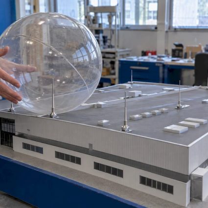
Under NF C 17-102, the area protected by an ESE terminal is a surface of revolution around the terminal axis. It is defined by protection radii at the heights considered. Those radii depend on four things: the features of the building, the height of the terminal, the efficiency of the terminal and the selected protection level.
Three consequences follow for placement:
- A higher protection level shrinks the radius. A site needing the most stringent level will need more terminals, or taller ones, to cover the same roof.
- The radius shrinks as you go down. The terminal protects a cone-like volume. Equipment at a lower elevation sits closer to the axis of coverage than the roof-level footprint suggests, and the calculation must be made at the height where the equipment actually is.
- Efficiency is a product property. The radius you can claim depends on the tested performance of the specific terminal. You cannot swap one terminal for another on the drawing without redoing the calculation.
This is why a placement plan should always come with a calculation note, not just marks on a roof drawing.
Conventional systems: capture points and meshed cages
Not every building uses an ESE terminal. For conventional air-terminal systems, the French engineering guide published by Cahiers Techniques du Bâtiment says the external system uses a capture point or a cage arrangement adapted to the roof, with mesh dimensions from 5 m to 20 m according to protection level. A tighter mesh corresponds to a more demanding level.
When does a meshed cage make sense? Typically on large, flat or low-slope roofs, where a few isolated rods would leave long unprotected distances and where a lot of equipment sits across the surface. Rods and meshes can also be combined. We supply the components for this approach, including conductor clamps and fixings for the connections along the cage.
For a side-by-side look at the frameworks themselves, our lightning standards page lays out how the French and international documents relate, and the article on electrical protection standards with real examples shows them applied.
Down conductors and earthing belong in the same plan
A rod placed without a clean path to ground is half a system. NF C 17-102 requires the design to settle the air-terminal positions, the down-conductor routes and the type and location of the earth termination together, once the protection level is known.
The same French building guide describes two down conductors for each simple or ESE lightning rod, placed on two different façades. The route should be the shortest and straightest practicable, with no upward runs. That has direct consequences for where you put the rod:
- A rod positioned in the middle of a roof with no access to two façades forces long, winding conductor runs.
- A rod near a corner or edge may give two short, direct routes on different façades.
- Architects should know early where conductors will be visible, so façade design can accommodate them.
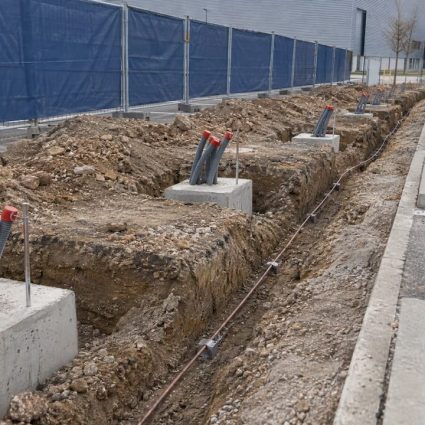
Our down conductor range and the flexible conductors are made for routes that have to follow the building’s shape. At the bottom, the earthing range completes the path, and for sites with poor soil conditions, deep earth grounding drilling is the answer to consider. For upkeep of the ground side, see our guide on maintaining grounding systems.
Site survey: neighbors, utilities and special zones
A good survey looks beyond the roof. Taller neighboring structures, trees, masts and adjacent buildings change what the terminal is exposed to and where conductors and electrodes can physically go. Below grade, buried services decide where trenches and earth electrodes can run. Even something as ordinary as fire line and hydrant servicing shows how much underground infrastructure a site can carry, and why a survey should map it before earthing is drawn.
Some sites need extra care on top of the standard approach. Where flammable atmospheres are present, placement interacts with hazardous-zone classification, and we explain how IEC 62305 works on French ATEX sites with isolated systems. For facilities with very sensitive equipment, our highly sensitive site design example shows how placement, conductors and surge protection are laid out together.
A worked placement sequence
Here is the order we follow on a typical industrial or commercial building:
- Collect the documents: roof plans, elevations, equipment layout, structural details and the use of the building.
- Run the risk analysis: this gives the protection level required.
- Walk the site: list towers, ridges, chimneys, extractors, photovoltaic arrays, terrace rooms and standalone structures.
- Choose the system type: ESE terminal, conventional rods, meshed cage or a combination.
- Set height and position: confirm the 2 m minimum for ESE terminals above the protected area, then calculate the protection radii at the heights that matter.
- Plan conductors and earthing: two down conductors per rod on different façades, shortest straight routes, with the earth termination located at the same time.
- Add surge protection where the analysis calls for it: a rod handles direct strikes, while equipment inside also needs protection from overvoltages. See our surge protection devices.
- Document and verify: record the as-built layout and schedule inspections.
Skipping step 2 or step 5 is the most common reason a drawing looks right and performs poorly.
Our perspective on placement
We have been working on lightning protection since 1955, and the pattern we see most often is simple: placement gets decided too late and too casually. A rod is added once the roof is finished, the conductor route is whatever space remains, and the earthing is treated as a separate job.
Our view is that placement is an engineering output, not a drawing exercise. It starts from the risk analysis, it is confirmed by calculation of protection radii, and it is inseparable from the down conductors and the earth termination. That is why we offer the whole chain: risk analysis and technical study, installation, verification and maintenance, along with the rods, masts, conductors and earthing components themselves.
Our R&D center keeps our terminals and methods aligned with changing standards and climate conditions, and our experience across more than 280,000 installations informs how we handle difficult sites: stepped roofs, crowded rooftops, sensitive process areas. We would rather help a client get the position right at design stage than correct it after commissioning.
INDELEC
Keeping the placement effective: inspection and maintenance
A correct placement only stays correct if the system is checked. NF C 17-102 calls for verification at four moments: initially after installation, periodically, after structural modification or repair, and after a lightning strike.
The periodic intervals depend on the protection level:
| Protection level | Visual inspection | Complete inspection |
|---|---|---|
| I and II | Every year | Every 2 years |
| III and IV | Every 2 years | Every 4 years |
| Critical systems | Not applicable | Complete inspection every year |
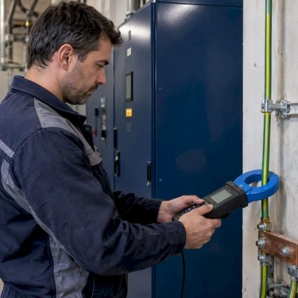
Checks cover damage, corrosion, continuity, bonds, separation distances, earth resistance and terminal operation. Findings are reported and faults corrected promptly. Placement ties into this: a new rooftop unit, a photovoltaic array or an extra floor changes the geometry, which is exactly the situation where the standard calls for a fresh verification. A strike counter helps maintenance teams know when a strike has occurred and an inspection is due.
Work with us on your next placement study
If you manage an industrial plant, a commercial building or public infrastructure and need rod positions that stand up to the standard, we can take it from risk analysis through installation and maintenance. See our lightning protection services for the full scope, or browse our lightning rods range.

For an overview of how we apply these steps on real sites, read our lightning protection system application page. If budget is your first question, our article on lightning rod cost in France explains what drives it.
FAQ
Where is the best place to put a lightning rod on a building?
At the highest exposed points: ridges, chimneys, towers, terrace rooms and roof equipment. The final positions come from the risk analysis and the protection-radius calculation. For an ESE terminal, the tip must be at least 2 m above the area it protects.
How many down conductors does a lightning rod need?
The French building guide describes two down conductors per simple or ESE lightning rod, placed on two different façades. Routes should be as short and straight as practicable, with no upward runs.
How far does one lightning rod protect?
There is no single figure. Under NF C 17-102 the protected area is a surface of revolution around the terminal axis. Its radii depend on the building, the terminal height, the terminal efficiency and the protection level, so the radius is calculated for each case.
How often should lightning protection be inspected?
After installation, periodically, after structural changes or repairs and after a strike. NF C 17-102 gives a visual check every year for levels I and II and every 2 years for levels III and IV, with complete inspections every 2 and 4 years respectively.
Sources
- NF C 17-102 (1995, interpretations 2001 to 2009)
- NF C 17-102, September 2011 edition
- ADEE, Réglementation Foudre France (2017)
- AFNOR, NF EN IEC 62305-1
- Cahiers Techniques du Bâtiment, Le paratonnerre, protection normalisée contre la foudre
- Fire line and hydrant servicing