One Strike, One Inspection: Lightning Counters for French ICPE
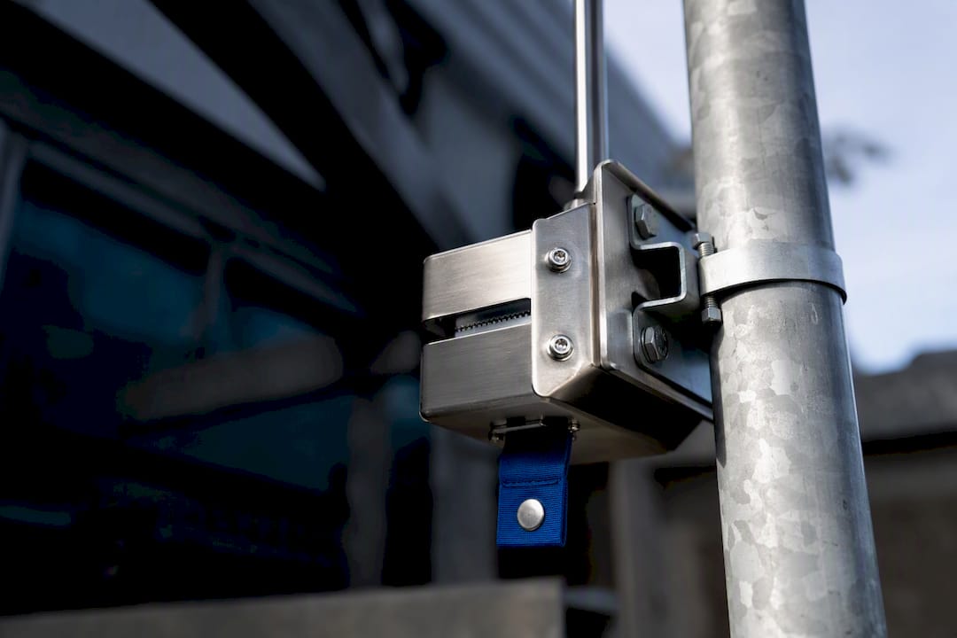
A lightning impact counter is a small device clamped to a down-conductor that logs every confirmed lightning current pulse strong enough to cross its trigger threshold. When the count goes up, the extraordinary inspection clause of IEC 62305-3 kicks in, and for classified sites in France, the 19 July 2011 decree adds a recordkeeping obligation on top of that.
TL;DR:
- Counters typically trigger around 3 kA, filtering out minor transients, and only record confirmed lightning strikes passing through the monitored conductor.
- French law mandates recording thunderstorm events with date and localization, either via onsite counters or third-party regional detection services like Météorage.
- Proper installation requires placing the counter in series on the down-conductor with correct mounting, connection quality, and thorough verification of the entire grounding path.
- A rising counter indicates a lightning current exceeded the trigger threshold but does not specify the strike’s magnitude or damage level.
- Regular inspection and maintenance of counters, including visual checks, continuity testing, and photo records, are essential to maintain compliance and ensure reliability over the service life.
Table of Contents
- How a Compteur d’Impacts Foudre Detects and Records a Strike
- When French Law and IEC Standards Require a Counter
- Choosing the Right Counter Type and Specs for Your Site
- Mounting the Counter So Every Strike Actually Gets Recorded
- What a Rising Count Actually Tells You (and What It Doesn’t)
- Combining Onsite Counters With Regional Detection Networks
- Keeping a Lightning Counter Accurate Over Its Service Life
- The Indelec Approach to Lightning Impact Monitoring
- Passive or Connected: A Technical Take on the Real Trade-off
- Specifying, Installing, and Maintaining Your Counter Setup
- Standards and Services Worth Bookmarking
- Sources
How a Compteur d’Impacts Foudre Detects and Records a Strike
A compteur d’impacts foudre works on a simple physical principle: current flowing through the down-conductor generates a magnetic field, and the counter’s sensor reacts once that field crosses a set threshold. No power supply, no batteries, no electronics required for the basic mechanical version. That’s the whole appeal of the passive design: it sits on the conductor for decades and just clicks forward each time a real strike passes through.
The catch is that a counter tells you a strike happened, not how big it was. IEC 62561-6 classifies these devices as lightning strike counters (LPSC) and defines their trigger behavior, with many models set to fire around 3 kA. That threshold matters because it filters out induced surges and minor transients that aren’t true lightning current events, so the number on the register reflects actual strikes to the structure, not electrical noise on the line.
What this means in practice for facility engineers:
- A count of “1” tells you at least one strike exceeded the trigger current. It does not tell you if that strike carried 5 kA or 150 kA.
- The counter cannot pinpoint exactly where on the structure the strike attached, only that current passed through the monitored conductor.
- A jump from 3 to 4 on the register is functionally identical, in terms of required response, to a jump from 40 to 41.
Some newer electronic counters go further, recording a timestamp and even a rough peak current estimate alongside the count, which changes how you use the data downstream but doesn’t change the core detection principle.
When French Law and IEC Standards Require a Counter
Classified installations under France’s ICPE framework fall under a specific obligation: the 19 July 2011 decree requires these sites to record thunderstorm activity, including datation and, where possible, localization of events. That’s a legal recordkeeping duty, not a suggestion, and it applies whether the site fulfills it with hardware on the down-conductor or a subscription service.
Separately, IEC 62305-3 Clause 7 sets a maintenance rule that applies regardless of ICPE status: any known lightning strike to a structure triggers an extraordinary inspection. A counter is the practical way most sites get that “known strike” signal, since without one, nobody necessarily notices a strike occurred until something fails.
Regulatory snapshot: ICPE sites need dated, localized thunderstorm records under the 2011 decree. Every LPS, regardless of classification, needs an extraordinary inspection after a known strike under IEC 62305-3 Clause 7.
There’s a meaningful distinction worth flagging here between two compliance paths:
- Onsite counters give you a direct, hardware-based confirmation of current through your specific down-conductor, with no ongoing subscription cost.
- Third-party tele-compteur services, like the one Météorage operates, deliver localized impact lists and maps for a site radius, satisfying the datation and localization requirement without installing anything on the structure.
Either path can satisfy the 2011 decree’s intent, but your documentation trail needs to show which method you’re using and that it’s actually producing records, not just installed and forgotten.
Choosing the Right Counter Type and Specs for Your Site
Not every counter fits every site, and procurement documents that just say “lightning counter” without specs invite the wrong product showing up on a pallet. Four broad device classes cover most installations:
- Mechanical passive counters. No power source, simplest design, longest service life with zero maintenance burden. Ideal for remote or unmanned structures where nobody visits often.
- Electronic timestamped counters. Add a clock and internal battery to log when each event occurred, which matters enormously when you’re trying to correlate a count with a specific storm night.
- Connected telemetry counters. Push data to a remote system or dashboard automatically, removing the need for a technician to physically read the register.
- Surge counters. A related but distinct category that tracks surge protective device operations rather than direct strikes to the LPS, useful for a complete picture of electrical stress on the building.
When you write a spec for a bid or acceptance test, pin down these values explicitly:
- Minimum trigger current (commonly around 3 kA, per IEC 62561-6)
- Maximum current withstand rating
- IP rating for the enclosure (IP65 is common for outdoor down-conductor mounting)
- Operating temperature range
- Register capacity (how many events it can log before rollover)
- Datation resolution and clock accuracy, for timestamped models
- Battery life expectancy, where applicable
- Mounting compatibility with your specific conductor diameter and clamp style
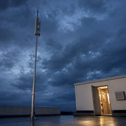
An industrial site with a staffed maintenance crew and a monthly walk-around schedule can run comfortably on a mechanical register. A coastal or offshore installation exposed to salt air needs an IP65-rated enclosure at minimum and stainless hardware. An unmanned substation or remote telecom tower is where connected telemetry earns its higher price tag, since nobody’s driving out to read a dial.
Mounting the Counter So Every Strike Actually Gets Recorded
Placement is not a minor detail. A counter has to sit on a conductor path where every amp of strike current is guaranteed to pass through it, which usually means installing it in series on the down-conductor between the air terminal and the earth-termination system.
Get the placement wrong and the counter becomes decorative. Here’s what to check during installation:
- Confirm there’s no parallel conductor path bypassing the counter. If current can split and take another route to ground, your register undercounts.
- Use the manufacturer’s specified clamp type for your conductor diameter and material, whether that’s round copper, flat tape, or aluminum.
- Orient the device per the manufacturer’s mounting diagram. Some models are polarity-sensitive or have a preferred vertical alignment for the internal mechanism.
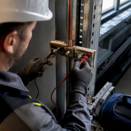
- Verify conductor continuity on both sides of the counter with a continuity tester before closing up the installation.
- Torque clamp connections to the specified value. Loose clamps introduce resistance and can eventually arc, which defeats the point of the whole system.
Pro Tip:Before final sign-off, walk the entire down-conductor route with the as-built drawing in hand and physically confirm there’s no secondary bonding point creating an alternate path to ground upstream of the counter. This single check catches the most common installation error on multi-conductor structures.
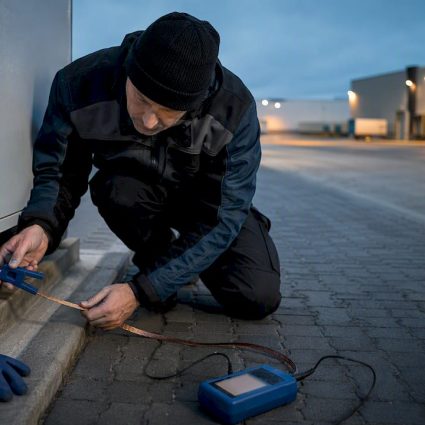
Commissioning should include a documented visual inspection, a continuity check, and a photo record of the mounted counter’s serial number and initial register reading. That baseline reading matters later. Without it, you have no way to prove how many strikes occurred between installation and your first maintenance visit.
What a Rising Count Actually Tells You (and What It Doesn’t)
A count increase proves one thing: current above the trigger threshold passed through that conductor. It does not tell you the strike’s magnitude, its exact attachment point on the structure, or whether any component actually suffered damage. Treating every incremented digit as an emergency is overkill; ignoring it entirely is a compliance and safety gap.
Here’s the practical sequence to follow once you notice the count has moved:
- Log the event. Record the new count, the date you observed it, and cross-reference against Météorage impact data or site weather logs to establish an approximate strike date.
- Scope the inspection. IEC 62305-3 Clause 7 calls for an extraordinary inspection after a known strike, which should cover joints, clamps, and earth electrode connections even when nothing looks visibly damaged.
- Decide targeted versus full inspection. A single count increment on a simple structure might warrant a targeted check of the affected down-conductor and its bonds. Multiple counts across several conductors, or a site with known corrosion issues, justifies a full LPS inspection.
- File the record. Timestamped logs, inspection findings, and any corrective action belong in the maintenance file that standards compliance will eventually ask to see.
Reconciling your onsite count with an external detection report is where the picture gets sharper. If your counter shows one event but Météorage’s regional data shows three strikes within a kilometer of your site that same night, that’s worth investigating rather than dismissing as a discrepancy.
Combining Onsite Counters With Regional Detection Networks
Onsite counters and regional detection networks solve two different problems, and running them together closes most of the gaps either one leaves on its own. The counter confirms current actually passed through your specific structure. A detection network gives you the broader picture: where storms tracked, how many ground strikes occurred nearby, and precise timestamps you can cross-check against your own register.
Météorage’s tele-compteur service illustrates the pattern well: it delivers localized impact lists and maps for a site radius, typically defaulting to a 2 kilometer zone, which gives facility teams datation and localization without installing additional hardware. For sites already running mechanical counters, adding this kind of subscription doesn’t duplicate effort. It adds context.
Integration in practice tends to follow a few patterns:
- Daily or next-day report pulls that get filed alongside maintenance logs automatically.
- API feeds into a facility monitoring dashboard for teams managing multiple sites.
- Alerting workflows that flag when a storm cell crosses within a defined radius, giving staff a heads-up before the counter even registers anything.
- Post-storm reconciliation, comparing the onsite register against the network’s event list to confirm nothing was missed.
The operational payoff is straightforward: earlier warning ahead of active storm cells, better scheduling of maintenance crews, and faster verification once a storm has passed instead of waiting for a scheduled walk-around to notice the counter moved.
Keeping a Lightning Counter Accurate Over Its Service Life
A counter that’s been ignored for five years is a liability disguised as a compliance tool. Routine maintenance doesn’t need to be elaborate, but it does need to happen on a schedule and get documented every time.
Build your inspection cadence around these checkpoints:
- Physical condition of the enclosure, clamp, and mounting hardware, checking for corrosion, cracking, or loosening.
- Display or register legibility, confirming the count is readable and matches the last logged value plus any known events.
- Battery status on electronic or connected models, replaced proactively rather than waiting for failure.
- Seal integrity on IP-rated enclosures, since a compromised gasket defeats the weatherproofing rating entirely.
- Conductor continuity through the mounting point, re-verified at each visit.
Functional acceptance tests during routine maintenance should confirm the device still triggers correctly, which for electronic models may mean a manufacturer-supplied test procedure rather than waiting for an actual strike to prove it works.
Pro Tip:Photograph the register reading at every maintenance visit, timestamped, and file it with the visit report. This creates an unbroken chain of evidence that’s far more convincing to an auditor or insurer than a maintenance log that just says “counter checked, OK.”
Replacement criteria should be built into your LPS lifecycle plan from the start. Mechanical counters can often run the life of the structure with no intervention, but electronic and connected models have battery and component lifespans that need to be tracked and budgeted for, not discovered the hard way during a post-strike inspection when the unit turns out to be dead.
The Indelec Approach to Lightning Impact Monitoring
A specialized company in lightning protection since the mid-20th century, the specification of counters is considered as part of broader discussions about the long-term performance of a structure’s protection system, not just at commissioning. A counter without a properly designed down-conductor and grounding system behind it is just a number that doesn’t mean much.
The scope on a typical lightning protection project may cover:
- Risk assessment to determine whether a site needs a counter, a detection subscription, or both
- Design and installation of air terminals, down-conductors, and grounding systems
- Specification and integration of counters into the broader lightning protection system
- Maintenance and inspection contracts incorporating counter checks into scheduled visits
- Certification documentation linking counter readings to compliance records.
The practical questions clients raise most often center on retrofit feasibility (can a counter be added to an existing conductor without disturbing an operating facility) and on how a mechanical counter’s simplicity trades off against a connected model’s remote visibility for a site that’s rarely staffed.
Passive or Connected: A Technical Take on the Real Trade-off
Mechanical counters win on lifecycle cost. No battery, no subscription, decades of service with essentially zero operating expense. That makes them the right default for staffed sites where someone walks the perimeter regularly anyway.
Connected and timestamped counters earn their premium on auditability. For a remote substation or an unmanned tower, a passive register that nobody reads for months defeats the purpose. Combining a basic onsite counter with a Météorage-style detection subscription tends to make sense once a site has both compliance exposure under the 2011 decree and enough operational value at stake to justify paying for regional context on top of the local confirmation.
— INDELEC
Specifying, Installing, and Maintaining Your Counter Setup
Getting the right counter on the right conductor, mounted correctly and maintained on schedule, is exactly the kind of detail that separates a compliant lightning protection system from one that just looks compliant on paper. Indelec handles this as part of a full lightning protection scope, not as an afterthought bolted onto an existing installation.

Services may cover the full process from initial risk assessment through counter and lightning protection system specification, installation, telemetry integration where needed, and ongoing maintenance contracts that maintain current and defensible inspection records. This can simplify contacts by reducing the need to coordinate multiple vendors separately.
If your site needs a risk assessment to determine what level of monitoring actually makes sense, or you’re ready to move on a full lightning protection system installation, reach out to discuss your structure’s specific down-conductor layout and compliance timeline. A quick site review is usually enough to scope out whether you need a simple mechanical counter, a connected model, or a combination with a detection subscription.
Standards and Services Worth Bookmarking
For the regulatory text itself, the 19 July 2011 decree sets the ICPE recordkeeping requirement. IEC 62305-3 and IEC 62561-6 govern inspection triggers and counter classification. Météorage’s tele-compteur service offers a hardware-free compliance path, and Indelec’s lightning standards reference walks through how these pieces fit together for a specific installation.
Sources
- Legifrance — Décret 19 July 2011 (ICPE and lightning risk)
- Météo‑France Services / Météorage — Télé-Compteur: Impact de Foudre
- TrilPeak — Lightning Strike Counter (standards and inspection role)