Atmospheric Discharges Explained: What They Are and Why They Matter
Atmospheric electrical discharges are rapid transfers of electric charge through the air, spanning everything from the faint blue glow of corona on a power line to the full violence of a lightning bolt and the ghostly red sprites flickering 60 miles above a thunderstorm. The main categories are: corona and brush discharge, streamers and partial discharges, lightning (intra-cloud, cloud-to-cloud, cloud-to-ground, and upward), and transient luminous events (TLEs) such as sprites, blue jets, and elves. The single most important safety principle across all of them is the same: control where the current flows. That means grounding, distance, and surge protection — in that order of priority.
Two numbers anchor everything that follows:
- ≈3×10⁶ V/m — the conventional dielectric breakdown threshold in air at sea level, the field strength at which electrons accelerate fast enough to ionize the air around them and trigger a self-sustaining discharge
- ~400,000 volts — the ionosphere’s potential relative to Earth’s surface, maintained continuously by the global network of thunderstorms
Even when no storm is overhead, the atmosphere carries a weak fair-weather conduction current of roughly 2 picoamperes per square meter. That background field is why sensitive electronics benefit from consistent surge protection year-round, not only during storms.
Key Takeaways
Atmospheric electrical discharges span from sub-breakdown corona to full lightning and high-altitude TLEs, and every effective protection strategy rests on controlling current paths through a coordinated system of air terminals, grounding, bonding, and surge protection.
| Point | Details |
|---|---|
| Breakdown threshold | Air breaks down at ≈3×10⁶ V/m at sea level; this threshold underpins all lightning protection engineering. |
| IC flashes dominate | Intra-cloud flashes outnumber cloud-to-ground strikes by roughly 5–10 times; CG strikes are the minority but cause most ground-level damage. |
| Return-stroke energy | Negative CG return strokes average ~30–40 kA and reach ~28,000 K, explaining why a defined low-impedance current path is non-negotiable. |
| Protection is systemic | Air terminal + down conductor + grounding + equipotential bonding + SPDs must work together; any missing element creates a failure point. |
| Indelec’s approach | Indelec delivers the full lifecycle from risk assessment and soil testing through installation, verification, and scheduled maintenance for compliant, resilient systems. |
Table of Contents
- How does charge separation form in the atmosphere?
- What are the main types of atmospheric discharges?
- How does a discharge actually form? Streamers, leaders, and the breakdown field
- Where and when are atmospheric discharges most frequent?
- What are the real impacts of atmospheric discharges?
- How do engineers protect buildings and systems from lightning?
- What should you do during a thunderstorm?
- What are the open research questions in atmospheric electricity?
- How do professionals assess lightning risk and design protection systems?
- Why the physics of atmospheric discharges should change how you think about protection
- Indelec’s lightning protection services: from risk assessment to commissioning
- Sources
How does charge separation form in the atmosphere?
The short answer: ice collisions inside a thunderstorm do most of the work. When graupel (soft hail) collides with smaller ice crystals in the presence of supercooled water droplets, charge transfers at each contact. Graupel tends to carry negative charge downward while lighter ice crystals carry positive charge upward, driven by the storm’s updrafts. The result is a layered charge structure: a large positive region near the storm’s top, a dominant negative region in the middle levels, and a smaller positive pocket near the base. When the electric field between those regions exceeds the local breakdown threshold, a discharge follows.
Updraft strength matters enormously. Vigorous convection keeps the ice-crystal and graupel populations in the mixed-phase zone (roughly −10°C to −25°C) long enough to build up charge. Weaker storms produce fewer flashes; supercells with sustained updrafts above 30 m/s can produce hundreds of flashes per hour.
Thunderstorms are not the only trigger. Volcanic plumes generate intense electrification because ash and ice particles collide in the eruption column, producing spectacular lightning directly above the vent. Intense wildfires loft enough charged particulates to create pyrocumulonimbus clouds capable of their own lightning. Dust storms and industrial aerosol plumes can also enhance local electric fields, though they rarely reach full breakdown without additional convective energy.
Understanding thunderstorm electrification matters practically because it explains why a single lightning rod is never enough. The charge distribution spans the entire storm volume, and a discharge can initiate almost anywhere within it.
What are the main types of atmospheric discharges?
The discharge family is wider than most people realize. NSSL/NOAA’s lightning type summaries confirm that intra-cloud (IC) flashes outnumber cloud-to-ground (CG) flashes by roughly 5–10 times, depending on the storm. Most of what you see as a general brightening of a cloud is IC activity — the bolt-to-ground is actually the minority event.
| Discharge type | Typical altitude / location | Current / energy characteristics | Visual cue |
|---|---|---|---|
| Corona / St. Elmo’s fire | Surfaces and sharp points at ground or tower level | Microamperes to milliamperes; no full breakdown | Blue-white glow, hissing sound |
| Streamers / partial discharges | Gap between electrodes or cloud base and ground | Sub-breakdown; localized ionization | Faint filaments, often invisible |
| Intra-cloud (IC) | Within cloud, 2–10 km altitude | Tens of kA; comparable to CG | Sheet illumination inside cloud |
| Cloud-to-cloud (CC) | Between separate clouds | Tens of kA | Visible channel between cloud masses |
| Negative CG (−CG) | Cloud base to ground | ~30–40 kA average return stroke | Forked bolt, downward branching |
| Positive CG (+CG) | Upper cloud to ground | Often >100 kA; longer duration | Single bright channel, often distant |
| Upward lightning | Tall structures to cloud | Triggered by local field enhancement | Upward-branching channel from tower |
| Sprites | ~50–80 km altitude | Weak currents; millisecond duration | Red jellyfish shapes above storm |
| Blue jets | ~20–40 km altitude | Narrow blue cone from cloud top | Blue upward cone |
| Elves | ~80–90 km altitude | Disk-shaped, sub-millisecond | Faint expanding ring |
A few details worth knowing:
- “Sheet lightning” is simply an IC or CC flash illuminating the cloud from inside — no distinct channel is visible from the ground.
- “Bolt from the blue” describes a CG flash that travels horizontally for tens of kilometers before striking ground well outside the storm’s visible boundary. It is one reason the “30-30 rule” (seek shelter when thunder follows lightning in under 30 seconds) matters: the storm is closer than it looks.
- Corona and St. Elmo’s fire are partial discharges, not full breakdown. They appear on ship masts, aircraft wings, and power-line hardware when the local field is high but not yet at the 3×10⁶ V/m threshold. As the IIP series review on electrical discharges in air explains, the transition from corona to streamer to full arc depends on local space charge geometry and gap length — which is why sharp points on structures concentrate field and need careful treatment in protection design.
- Upward lightning deserves special attention for facility managers. Tall structures — towers, wind turbines, high-rise buildings — can initiate upward leaders and effectively become the trigger point for a discharge. A professionally audited grounding and equipotential bonding system is not optional for these structures; the protected object itself can become the initiation site.
How does a discharge actually form? Streamers, leaders, and the breakdown field
The sequence from calm air to a full lightning bolt runs: seed electrons → electron avalanche → streamer → leader channel → return stroke. Each stage is faster and more energetic than the last.
A free electron in a strong electric field accelerates and collides with a neutral air molecule, knocking out another electron. Those two electrons accelerate and collide again — a Townsend avalanche. When the space charge from the avalanche distorts the local field enough to sustain its own propagation, the process transitions to a streamer: a thin, self-propagating ionized channel. Streamers from opposite polarities can meet and form a conducting path, but for large gaps (cloud-to-ground distances of 1–5 km), a more organized leader channel develops instead.
The stepped leader advances in discrete steps of roughly 50 m, pausing for ~50 microseconds between steps. As it approaches ground, upward-connecting leaders rise from tall objects and sharp points. When one connects, the circuit closes and the return stroke propagates upward at roughly one-third the speed of light, carrying the ~30–40 kA of current that heats the channel to around 28,000 K — hotter than the sun’s surface. That rapid heating produces the shock wave we hear as thunder.

The breakdown field and altitude dependence. At sea level, air breaks down at approximately 3×10⁶ volts per meter. At higher altitudes, air density drops, and so does the breakdown threshold — meaning discharges can initiate at lower absolute field strengths. This is one reason TLEs occur far above the storm: the mesosphere and lower ionosphere are thin enough that even relatively weak fields can drive ionization. Dwyer and Uman’s 2014 review provides the canonical treatment of this multi-stage process and the engineering thresholds that follow from it.
Runaway electrons add a layer of complexity. In very high fields, some electrons gain energy faster than they lose it through collisions — they “run away” to relativistic speeds. These relativistic feedback mechanisms are thought to contribute to the initial breakdown phase and are directly linked to terrestrial gamma-ray flashes (TGFs), bursts of gamma radiation detected by satellites above active thunderstorms. For most engineering purposes, the conventional 3×10⁶ V/m threshold remains the working figure, but runaway physics explains phenomena that classical breakdown theory cannot.
Statistic callout: A single cloud-to-ground event can involve components ranging from nanoseconds (fast initial pulses) to nearly a second (continuing current), spanning more than nine orders of magnitude in time. Protection systems must handle both fast transient and sustained currents, which is why a complete system requires both surge protection devices and a low-impedance grounding path.
Where and when are atmospheric discharges most frequent?
Tropical regions dominate global flash counts. The highest flash densities occur over central Africa (particularly the Congo Basin), the Himalayan foothills, and parts of Central and South America — areas where deep convection is both intense and frequent. Temperate regions see strong seasonal peaks tied to summer convective activity, while polar regions have very low flash rates.
Key patterns:
- Afternoon and early evening see the highest flash rates in most continental regions, when surface heating peaks and convective instability is greatest.
- Coastal and orographic zones can have elevated rates because terrain forces moist air upward, triggering convection even when synoptic conditions are weak.
- Upward lightning is disproportionately common at tall structures in flat terrain (wind farms on plains, broadcast towers) because there are no competing tall objects to share the field enhancement.
For facility managers, local climatology is not just background knowledge. A site in a high-flash-density region faces a statistically higher annual strike probability than one in a low-density zone, and that probability feeds directly into the risk-assessment calculations that determine what protection system level is required under applicable standards. Long-term trends also matter: convective activity is shifting with changing climate patterns, and a risk assessment based on 30-year-old climatological data may underestimate current exposure.
Pro Tip:When commissioning a site risk assessment, ask the engineer to use the most recent available lightning location network data for your region — not just published climatological averages. Local flash density can vary by a factor of 3–5 within a single country.
What are the real impacts of atmospheric discharges?
The hazards fall into five categories, and the less obvious ones cause more casualties than the dramatic direct strike.
Human injury and fatality. Direct strikes are survivable more often than people assume, but they are not the leading cause of lightning casualties. Step potential is. When a lightning current enters the ground, it spreads radially outward. A person standing with feet apart straddles two points at different potentials; current flows up one leg and down the other. Victims can be tens of meters from the strike point. Crouching with feet together and minimizing ground contact is the correct outdoor response.
Structural damage. A return stroke carrying ~30–40 kA and reaching ~28,000 K can ignite roofing materials, shatter masonry, and split trees. Structures without a defined current path force the current to find its own route — through walls, plumbing, or structural steel — with unpredictable results.
Electrical systems and electronics. Conducted and induced surges travel through power lines, data cables, and metallic pipework. A strike several hundred meters from a facility can induce transient overvoltages sufficient to destroy unprotected control systems, PLCs, and communications equipment. The environmental and operational costs of a single control-system failure in an industrial plant routinely exceed the cost of a complete protection system.

Wildfires. Positive CG flashes, which carry higher peak currents and longer continuing current, are particularly effective at igniting dry vegetation. In fire-prone regions, lightning is a primary ignition source during drought conditions.
Atmospheric chemistry and radio effects. Lightning produces nitrogen oxides (NOₓ) that contribute to tropospheric ozone chemistry. It also generates broadband radio emissions (sferics) detectable globally, and the return stroke’s electromagnetic pulse can interfere with VLF communications and navigation systems.
Corona and partial discharges, though far less dramatic, cause slow degradation of high-voltage insulation and generate electromagnetic interference that can disrupt sensitive instrumentation. Routine inspection of high-voltage infrastructure catches this before it becomes a failure event.
How do engineers protect buildings and systems from lightning?
Protection is a system, not a device. An air terminal alone, without a low-impedance path to ground and coordinated surge protection, simply redirects the current into the structure rather than safely around it. The complete system has five interdependent layers.
Core components:
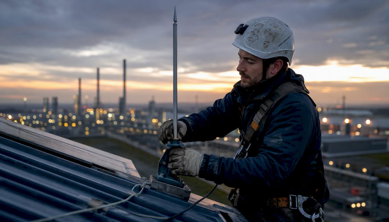
- Air terminals (lightning rods, including Early Streamer Emission types like the Prevectron3) intercept the discharge before it attaches to the structure itself. Placement follows standards-based geometry to define a zone of protection.
- Down conductors provide a defined, low-impedance path from the air terminal to the grounding system. Routing matters: sharp bends increase impedance and can cause side flashes to nearby metalwork.
- Grounding electrodes dissipate the current into the earth. Soil resistivity governs how many and what type of electrodes are needed. In high-resistivity soils, deep earth grounding drilling reaches lower-resistivity strata that surface rings cannot access.
- Equipotential bonding connects all metallic masses (structural steel, pipework, cable trays, equipment frames) to the same reference potential. Without bonding, the voltage difference between the grounding system and nearby metalwork during a strike drives dangerous side flashes.
- Surge protection devices (SPDs) are installed at the service entrance and at sensitive equipment panels to clamp transient overvoltages on power and data lines. They are the last line of defense against conducted and induced surges.
Site risk assessment checklist:
- Structure height, geometry, and construction material
- Local flash density (ground flash density, Ng, from lightning location network data)
- Soil resistivity measurements at multiple depths
- Occupancy type and consequence of failure (data center vs. storage shed carry very different risk tolerances)
- Presence of flammable or explosive materials
- Critical equipment inventory and its surge immunity ratings
- Existing grounding infrastructure and its condition
Standards compliance is not optional for most commercial and industrial structures. Professionals follow recognized international and national standards during design and installation, and third-party certification during commissioning provides documented evidence of compliance. Indelec’s lightning standards reference outlines the normative framework that governs system design.
Pro Tip:Schedule a maintenance inspection at least every two years — and after any confirmed or suspected strike. Grounding connections corrode, SPDs sacrifice themselves protecting equipment (and need replacement), and conductor fixings loosen. A protection system that was compliant at installation may not be compliant five years later without documented maintenance.
What should you do during a thunderstorm?
The top three actions: get inside a substantial building or hard-topped vehicle, avoid conductive contact with exterior surfaces, and protect electronics with surge protection devices or by unplugging them.
Outdoors:
- Move away from tall isolated objects (trees, poles, towers) — they attract upward leaders
- Leave open fields, hilltops, and water bodies immediately; water is an excellent conductor and flat terrain offers no shelter
- If caught in the open with no shelter, crouch low with feet together to minimize step potential exposure — do not lie flat
- Avoid metal fences, pipelines, and railway lines, which can conduct current from a distant strike
Indoors:
- Stay away from wired appliances, corded phones, and plumbing during active lightning
- Avoid windows and exterior doors
- Surge protectors on power strips help with minor transients; for serious protection, whole-building SPDs at the service panel are the correct solution
In vehicles:
- A metal-bodied car acts as a partial Faraday cage — the current travels around the exterior. Stay inside, keep windows up, and avoid touching metal parts of the door frame or steering column until the storm passes.
For facilities and outdoor operations:
- Establish a written lightning safety protocol with a defined suspension threshold (the 30-30 rule is a practical minimum: suspend operations when thunder follows lightning in under 30 seconds, resume 30 minutes after the last thunder)
- Maintain an emergency kit that includes a battery-powered weather radio
- Post clear signage at outdoor work areas identifying the nearest substantial shelter
What are the open research questions in atmospheric electricity?
The frontier topics are transient luminous events, terrestrial gamma-ray flashes, runaway electron physics, and the detailed mechanism of leader initiation — and all four remain genuinely unsolved at some level.
TLEs and TGFs. Sprites were only photographed accidentally in 1989; systematic study is barely three decades old. Satellite instruments like the Fermi Gamma-ray Space Telescope have confirmed that TGFs are real, frequent, and energetic enough to produce antimatter. The connection between specific lightning flash types (particularly positive CGs) and TLE generation is established, but the precise triggering conditions are still debated.
Leader initiation. Classical breakdown theory predicts that the fields measured inside thunderstorms should not be sufficient to initiate leaders. Yet lightning happens constantly. Runaway electron avalanches, cosmic-ray ionization, and hydrometeor-enhanced local fields are all proposed mechanisms, and the evidence for each is partial. Dwyer and Uman’s review frames this as one of the central open problems in atmospheric physics.
Measurement challenges. Leader networks can extend more than 100 km in large storm systems, and the relevant processes span nanoseconds to seconds. No single instrument captures the full picture. Lightning mapping arrays (LMAs) reconstruct 3D flash geometry from VHF emissions, but their spatial resolution degrades with distance. Balloon-borne electric field soundings provide in-situ data but sample only a tiny volume of the storm.
Observational advances. Low-light cameras on the International Space Station have produced the clearest images of sprites and elves to date. The ASIM (Atmosphere-Space Interactions Monitor) instrument on the ISS simultaneously detects TGFs, optical pulses, and radio emissions, allowing multi-messenger analysis of the same event. These datasets are beginning to constrain models in ways ground-based networks cannot.
The practical implication for engineers is that the physics of extreme events — very high-current positive CGs, long continuing current — is still being characterized. Conservative design margins in protection systems are not bureaucratic caution; they reflect genuine uncertainty about the upper tail of the current distribution.
How do professionals assess lightning risk and design protection systems?
The professional process follows a documented lifecycle: site survey → lightning exposure study → soil resistivity testing → system design → installation → verification and testing → scheduled maintenance. Skipping any step creates gaps that the remaining steps cannot compensate for.
The procurement process, step by step:
- Site survey. Physical inspection of structure geometry, height, materials, and existing electrical infrastructure. Identify all metallic masses requiring bonding.
- Lightning exposure study. Calculate the annual strike probability using local ground flash density data and the structure’s effective collection area. This feeds the risk-level classification.
- Soil resistivity measurements. Four-point Wenner method at multiple spacings and orientations. Results determine electrode type, depth, and configuration.
- System design. Select protection level (I–IV under applicable standards), specify air terminal placement, down conductor routing, grounding electrode configuration, bonding topology, and SPD coordination.
- Installation. Execute to design drawings with documented material traceability. Down conductor connections and grounding electrode installations are the most common points of non-compliance.
- Verification and testing. Measure grounding resistance, verify bonding continuity, inspect SPD condition, and issue test certificates. In many jurisdictions, test certificates are now compulsory for new installations and periodic re-inspection.
- Scheduled maintenance. Inspect at defined intervals, after confirmed strikes, and after any structural modification that changes the building’s geometry or adds new equipment.
What to request from a professional service provider:
- Written risk assessment report with flash density data source identified
- Soil resistivity test results with measurement locations mapped
- System design drawings with protection zone calculations
- Material specifications and traceability documentation
- As-built drawings reflecting any installation deviations
- Grounding resistance test certificates
- SPD installation records and rated discharge capacity
Indelec has been engineering protection for highly sensitive installations since 1955, with a dedicated R&D center that keeps its design methods current with evolving standards and climate data. For complex or high-exposure sites — airports, data centers, industrial plants — that combination of long field experience and active research capability is what separates a compliant installation from a genuinely resilient one.
Why the physics of atmospheric discharges should change how you think about protection
Most facility managers think about lightning protection the way they think about a smoke detector: install it, forget it, and hope it works when needed. The physics argues for a different mental model entirely.
A lightning discharge is not a single event. It is a sequence of processes spanning nine orders of magnitude in time, involving charge regions distributed across cubic kilometers of atmosphere, and capable of initiating from the structure you are trying to protect. The return stroke that causes visible damage is the end of a chain that started with ice collisions in a cloud, propagated through a stepped leader that sampled multiple potential attachment points, and terminated at the path of least impedance. Change the impedance landscape — through grounding, bonding, and air terminal placement — and you change where that path goes.
That is why the engineering response to atmospheric discharges is systemic. An air terminal without a grounding system is a current collector with nowhere to send the charge. A grounding system without equipotential bonding creates voltage differences that drive side flashes through walls and equipment. Surge protection devices without a coordinated grounding reference have no stable potential to clamp against. Each element depends on the others, and the weakest link determines the outcome.
The science also argues for humility about “solved” problems. Leader initiation, the upper tail of the current distribution, and the behavior of protection systems under multiple-stroke events are all areas where the engineering standards encode conservative assumptions precisely because the physics is not fully characterized. Indelec’s R&D investment is not marketing; it is a recognition that the standards will keep evolving as measurement science improves, and that installations designed to today’s best knowledge will need to be revisited.
Indelec’s lightning protection services: from risk assessment to commissioning
Atmospheric discharges present a quantifiable, manageable risk — but only when the protection system is designed to the specific exposure of the site, not to a generic template.

Indelec provides the full engineering lifecycle: site risk assessment, soil resistivity testing, system design to applicable standards, supply of air terminals (including the Prevectron3 with OptiMax technology), down conductors, grounding systems including deep earth grounding drilling for high-resistivity soils, equipotential bonding, and coordinated surge protection devices. Installation is followed by documented verification, test certificates, and scheduled maintenance programs. Technical training and certification support are also available for in-house engineering teams.
For industrial plants, infrastructure operators, and facility managers who need a compliant, resilient system rather than a checkbox exercise, the starting point is a site consultation. Contact Indelec’s engineering team to request a risk assessment and discuss the protection level your installation requires.
Sources
The sources below underpin the claims in this article and are worth consulting directly for deeper technical detail.
- The physics of lightning (Dwyer & Uman, 2014)
- Atmospheric electricity (UCAR educational resource)
- Severe Weather 101: Lightning Types (NSSL/NOAA)
- Presentation of electrical discharges in air (IIP series review)