Photovoltaic Panel Lightning Risk: What Engineers Must Know
TL;DR:
- Photovoltaic panel lightning risk involves direct lightning strikes and induced surges that can damage equipment or cause fires. Proper protection requires installing surge protective devices, ensuring comprehensive grounding, and conducting thorough risk assessments based on local lightning data. A layered approach, including external lightning protection, SPD installation at key points, and regular inspections, is essential for safety and system longevity.
Photovoltaic panel lightning risk is the potential for equipment damage, fire, or electrical failure caused by direct lightning strikes or lightning-induced surges on solar energy systems. Both threats are real, and both are underestimated by facility teams that focus only on physical strike protection. The consequences range from inverter failure and arc faults to full system loss and personnel injury. Standards like IEC 62305, IEC 61643-11, and NEC 690 define the protection requirements, and lightning risk to PV installations is now a primary concern for engineers designing or managing solar assets in 2026.
What is photovoltaic panel lightning risk, and why does it matter?
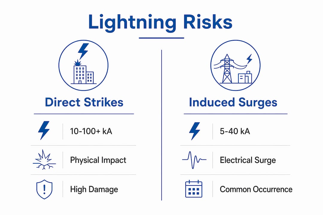
Photovoltaic panel lightning risk covers two distinct but related threats. The first is a direct strike, where lightning attaches to the array or its support structure and drives tens of thousands of amperes through the system. The second is an induced surge, where a nearby strike or grid switching event injects a transient overvoltage into the DC or AC wiring without any physical contact with the array.
Direct strikes carry 10–100+ kA of current. Induced surges typically reach 5–40 kA. Both magnitudes destroy unprotected equipment, but induced surges are far more frequent and account for the majority of inverter failures in the field.
The consequences of unmanaged lightning risk extend beyond hardware replacement. Arc faults can ignite fires in roof-mounted systems. Electrical shock hazards persist because PV panels generate DC voltage continuously, even during a storm. Facility managers who treat lightning protection as optional face equipment downtime, insurance claims, and potential liability for personnel injuries.
What are the direct and indirect lightning risks to PV panels?
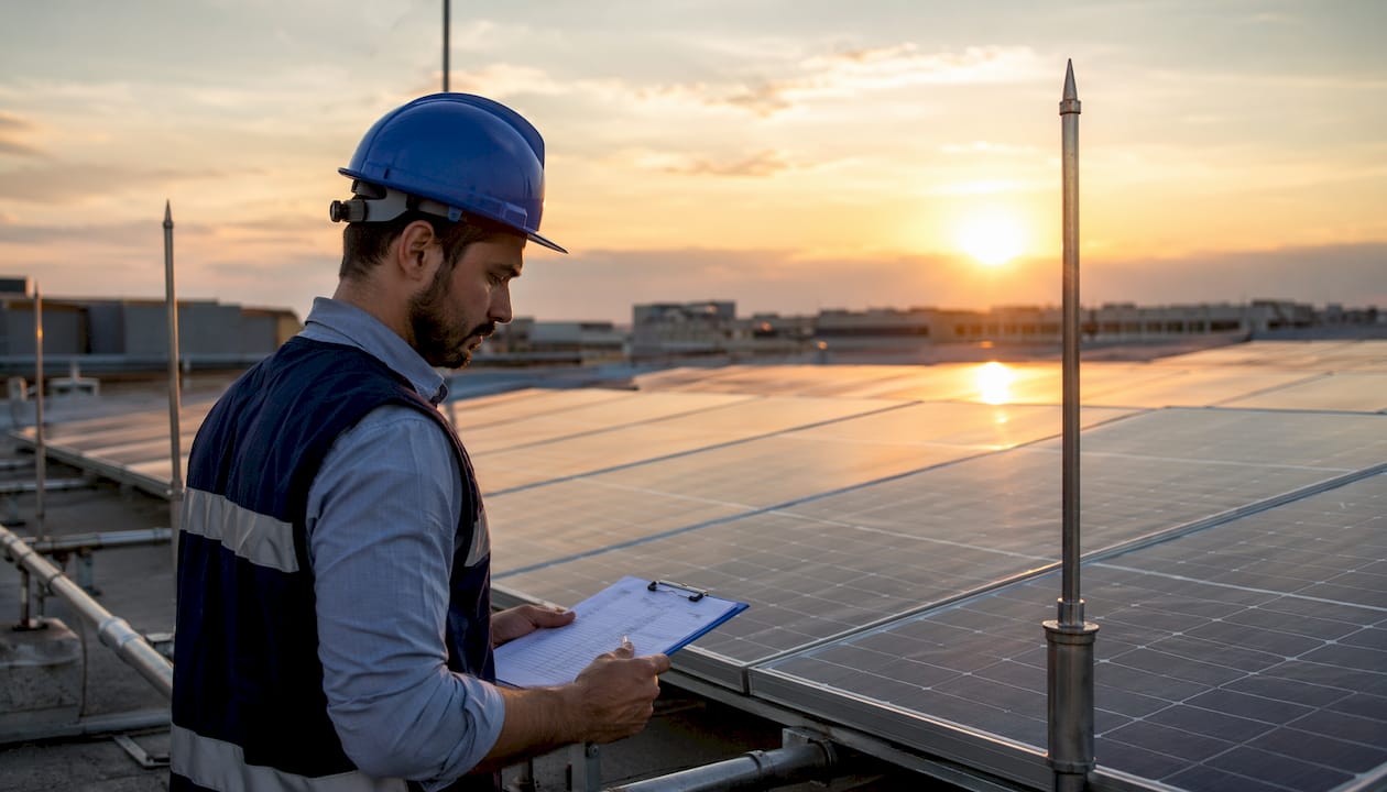
PV arrays are structurally vulnerable to both strike types. Their elevated, open geometry and long unshielded DC cable runs make them efficient lightning collectors. A rooftop array on a tall commercial building sits at the highest point of the structure. A ground-mounted utility array spans hundreds of meters of exposed conductor. Both configurations attract direct strikes and act as antennas for electromagnetic induction.
Direct strike mechanisms
A direct strike delivers a full lightning impulse current to the array. That current travels through the module frames, mounting rails, DC wiring, and into the inverter. Without a dedicated external lightning protection system (LPS) with air terminals and down conductors, the entire current path runs through the electrical equipment. The result is catastrophic failure of modules, combiner boxes, and inverters.
Induced surge mechanisms
Induced surges are subtler but more common. A lightning strike within several hundred meters of a PV installation generates a rapidly changing electromagnetic field. That field induces a transient voltage in any conductor loop formed by the DC wiring. Grid-side switching events produce similar transients on the AC output. Surge energy enters from unprotected sides of the inverter, causing catastrophic failure even when no direct strike occurs.
The geometry of the array determines the size of the conductor loop and therefore the magnitude of the induced surge. Long cable runs between the array and the inverter create larger loops and higher induced voltages. Minimizing cable loop area through careful routing is a first-line design measure, but it does not eliminate the need for surge protective devices.
How do surge protective devices mitigate lightning risks in PV systems?
Surge protective devices (SPDs) are the primary electrical defense against both direct and induced lightning threats in PV installations. The IEC 61643-11 standard and NEC 690/230.67 define three SPD types based on their test waveforms and installation location.
Type 1 SPDs are tested against the 10/350 µs waveform, which simulates a direct lightning impulse. Type 1 SPDs handling ≥12.5 kA are mandatory at Lightning Protection Zone (LPZ) boundaries where an external LPS is present. They absorb the partial lightning current that enters the electrical system at the service entrance or combiner box.
Type 2 SPDs are tested against the 8/20 µs waveform, which represents an induced surge. Type 2 devices rated at ≥5 kA protect against induced transients at the inverter’s DC input and AC output. They are required even when no external LPS exists, because induced surges occur independently of direct strikes.
Type 1+2 combined devices handle both waveforms in a single unit. Ground-mounted systems in high-lightning-density zones require Type 1+2 devices at the array combiner box and at the inverter AC output.
Placement follows LPZ boundaries defined in IEC 62305-4. Type 1 devices install at the boundary between LPZ 0 (outdoors, full lightning exposure) and LPZ 1 (inside the building or enclosure). Type 2 devices install at the LPZ 1/LPZ 2 boundary, which is typically at the inverter terminals.
Laboratory testing confirms that external SPDs extend inverter life by diverting over 90% of surge energy before it reaches sensitive electronics. Inverters without external SPDs can fail after as few as 7 surge impulses. That failure rate translates directly to unplanned downtime and replacement costs.
Pro Tip:Install SPDs on both the DC array side and the AC grid side of every inverter. Protecting only one side leaves the other as an open path for surge energy.
What are the essential grounding and earthing practices for PV installations?
Grounding is the foundation of any lightning protection system, but the standard 10 Ω grounding resistance target is insufficient for large or ground-mounted PV systems. Achieving 10 Ω alone does not guarantee safety. Electronic equipment often requires earthing resistance below 1 Ω, and step-voltage safety thresholds demand designs that meet 25 kV step-voltage limits.
The critical concept is equipotential bonding. All earthing systems on a site, including the PV array structure, the inverter enclosure, the building steel, and any external LPS earth electrodes, must connect to a single equipotential bonding network. Separate earthing systems at different potentials create dangerous voltage differentials during a lightning event.
Key grounding requirements for PV installations include:
- Soil resistivity analysis before electrode design. High-resistivity soils require deep-driven rods, horizontal ring electrodes, or chemical enhancement to achieve target resistance values.
- Equipotential bonding conductors connecting all metallic structures, cable trays, and equipment enclosures across the entire array footprint.
- Corner strike consideration for ground-mounted arrays. Equipotential bonding effectiveness depends on soil resistivity and strike location. Corner strikes produce the highest step voltages and require specific bonding conductor layouts.
- Compliance with IEC 62305-3 and IS 3043 for electrode design, conductor sizing, and bonding requirements.
Pro Tip:Commission a soil resistivity survey using the Wenner four-electrode method before finalizing your earthing design. A single measurement at one depth tells you almost nothing about actual electrode performance.
Meeting nominal resistance targets in low-resistivity soil does not mean the system is safe in all conditions. Full equipotential bonding across all earthing systems is required to prevent hazardous voltage differentials during a strike event.
How do rapid shutdown systems complement lightning protection?
Rapid shutdown systems address a specific hazard: the continuous DC voltage present in PV wiring even during emergencies. PV panels generate voltage whenever light hits them. That means DC wiring remains live during a lightning storm, a fire, or a maintenance response unless a shutdown system is active.
NEC 2017 and NEC 2020 mandate rapid shutdown to protect responders by reducing DC voltage to safe levels within 30 seconds of activation. This protects firefighters and emergency personnel who may need to access the roof or building interior.
Rapid shutdown systems do not replace SPDs or external lightning protection. They address the personnel safety hazard from continuous DC voltage. SPDs address the equipment damage hazard from transient overvoltages. Both systems are required, and they operate independently.
Facility managers should verify the following for compliance and safety:
- Rapid shutdown initiators are installed and tested per the applicable NEC edition.
- Arc fault circuit interrupters (AFCIs) are present on DC circuits to detect and interrupt arc faults before they ignite fires.
- Maintenance teams receive training on the DC voltage risks present in PV systems, including the fact that panels remain energized even after inverter shutdown.
- Shutdown procedures are posted at the service entrance and at the array disconnect.
Compliance with rapid shutdown is a safety requirement, not just a regulatory checkbox. First responders and maintenance teams depend on these systems functioning correctly.
What practical steps should facility managers take to assess and mitigate PV lightning risk?
A structured risk assessment is the starting point for any protection decision. IEC 62305-2 defines the methodology, which combines ground flash density (Ng), the collection area of the structure, and risk factor parameters to calculate the annual probability of damage. Systems in areas with Ng greater than 5 require higher protection levels, and rooftop PV on tall buildings often needs an integrated LPS.
The practical steps for facility managers are:
- Obtain local Ng data from the national meteorological authority or a certified lightning protection engineer. Ng varies significantly by region and determines whether a formal LPS is required.
- Calculate the collection area of the PV installation using the IEC 62305-2 method. Larger arrays and taller buildings have larger collection areas and higher strike probabilities.
- Select LPS and SPD types based on the calculated risk level. A low-risk rooftop installation may need only Type 2 SPDs. A high-risk ground-mounted plant requires a full LPS with air terminals, down conductors, earth electrodes, and Type 1+2 SPDs.
- Integrate lightning protection into the system design from the start. Retrofitting protection to an existing installation is more expensive and often less effective than designing it in from day one.
- Schedule periodic inspections of all SPDs, earth electrodes, and bonding conductors. SPDs have a finite service life and must be replaced after absorbing significant surge energy.
Pro Tip:Use the lightning risk assessment guide from Indelec to structure your IEC 62305-2 calculation. A documented assessment also satisfies insurance and regulatory audit requirements.
Daily grid transients pose a continual threat to inverter health comparable to lightning surges. This means SPD maintenance is not a once-per-decade task. Annual inspection of SPD status indicators and earth resistance measurements keeps the protection system functional between major weather events.
Key Takeaways
Photovoltaic panel lightning risk requires protection against both direct strikes and induced surges, using SPDs, proper earthing, and rapid shutdown systems working together.
| Point | Details |
|---|---|
| Two distinct threats | Direct strikes (10–100+ kA) and induced surges (5–40 kA) both damage PV systems without proper protection. |
| SPD type selection matters | Type 1 SPDs handle direct lightning impulses; Type 2 handles induced surges; both are required at correct LPZ boundaries. |
| Grounding alone is insufficient | The 10 Ω resistance target does not ensure safety. Equipotential bonding and soil resistivity analysis are required. |
| Rapid shutdown is not surge protection | NEC-mandated rapid shutdown protects personnel from DC voltage. It does not substitute for SPDs or an external LPS. |
| Risk assessment drives decisions | IEC 62305-2 methodology using Ng and collection area determines which protection level your installation requires. |
Indelec’s perspective on photovoltaic lightning protection
The most persistent mistake we see in the field is treating induced surges as a secondary concern. Facility teams invest in air terminals and down conductors, then install no SPDs at the inverter. The result is a system that survives a direct strike to the LPS but loses its inverter to the next induced transient from a strike 300 meters away.
The second mistake is treating grounding as a single-number target. We have assessed sites where the earth electrode measured well below 10 Ω, yet the installation had no equipotential bonding between the array structure and the building steel. During a strike, that voltage differential is enough to injure personnel and destroy equipment. The resistance number means nothing without the bonding network.
What actually works is a layered approach: external LPS where the risk assessment requires it, Type 1+2 SPDs at every LPZ boundary, full equipotential bonding across all metallic structures, and annual inspection of every component. No single layer is sufficient on its own. The lightning standards that govern this work exist because each layer addresses a failure mode the others cannot.
The industry is also seeing more ground-mounted utility-scale arrays in regions with high ground flash density. These installations require site-specific engineering, not catalog solutions. Soil resistivity varies across a large array footprint, and a single earth electrode design does not perform uniformly across the site. Engineers who treat every installation as unique, and who commission soil surveys and formal risk assessments, consistently achieve better protection outcomes than those who apply generic rules.
— Indelec
Indelec’s lightning protection solutions for PV systems
Indelec has specialized in lightning protection since 1955, and photovoltaic installations represent one of the most technically demanding application areas the company addresses. Every PV project involves a combination of direct strike risk, induced surge exposure, and continuous DC voltage hazard that requires an integrated protection design.

Indelec’s lightning protection system applications cover the full scope of PV protection: air terminals, down conductors, earth electrode design, SPD selection, and equipotential bonding. The company’s engineering team performs IEC 62305-2 risk assessments, specifies protection to the correct standard, and provides installation and ongoing maintenance services to keep systems compliant and functional. Facility managers and engineers working on new PV projects or auditing existing installations can contact Indelec for a site-specific consultation.
FAQ
What is the difference between a direct strike and an induced surge on a PV system?
A direct strike delivers full lightning current (10–100+ kA) physically to the array or structure. An induced surge is a transient voltage injected into the wiring by a nearby strike’s electromagnetic field, typically 5–40 kA, and occurs far more frequently than direct strikes.
Are Type 1 SPDs required on every PV installation?
Type 1 SPDs are mandatory at LPZ boundaries where an external lightning protection system is present, and for ground-mounted systems in high-lightning-density zones. Installations without an external LPS typically require Type 2 SPDs at minimum on both DC and AC sides of the inverter.
Does rapid shutdown replace surge protection for solar panels?
No. NEC-mandated rapid shutdown reduces DC voltage to protect emergency responders within 30 seconds. It does not divert surge energy or protect inverters from transient overvoltages. SPDs and rapid shutdown systems serve different functions and both are required.
How often should SPDs and earth electrodes be inspected on a PV system?
Annual inspection is the standard practice. SPDs have a finite service life and must be replaced after absorbing significant surge energy. Earth resistance measurements should be taken annually to confirm electrode performance has not degraded due to soil changes or corrosion.
What standard governs lightning risk assessment for PV installations?
IEC 62305-2 defines the risk assessment methodology, combining ground flash density (Ng), collection area, and risk parameters to determine the required protection level. NEC 690 governs electrical safety requirements for PV systems in the United States.