Lightning Pathways Explained for Engineers and Architects

TL;DR:
- Lightning does not follow the shortest path between cloud and ground, but branches probabilistically based on environmental factors. Proper protection requires understanding lightning channel formation, equipotential bonding, and adherence to conductor sizing standards to prevent failures. Field verification through rigorous testing ensures the system performs reliably under actual strike conditions.
Lightning does not pick the shortest path between cloud and ground. That assumption, while intuitive, leads to protection system failures that are entirely avoidable. Understanding lightning pathways explained as a physical process, what engineers formally call lightning channel formation and discharge, reveals a far more probabilistic, branching, and environmentally sensitive phenomenon. This guide breaks down the atmospheric physics, ties them directly to protection system design, and gives you the practical criteria that separate a compliant installation from one that actually performs under real strike conditions.
Table of Contents
- Key takeaways
- Lightning pathways explained: the physics of channel formation
- How lightning behavior shapes protection system design
- Implementation and testing in real projects
- Advances in understanding lightning initiation
- My perspective on what actually matters in the field
- How Indelec supports your lightning protection projects
- FAQ
Key takeaways
| Point | Details |
|---|---|
| Stepped leaders govern pathway formation | Lightning follows branched ionized channels in discrete jumps, not a single straight path downward. |
| Equipotential bonding is non-negotiable | Bonding all conductive elements to a common reference prevents dangerous side flashes and touch voltage during a strike. |
| Conductor sizing has minimum standards | Standards like DIN VDE 0100-540 specify minimum cross sections to handle actual lightning current magnitudes. |
| Loose bonds invalidate your design | A visually correct installation can fail if continuity testing reveals high-resistance or disconnected bonding joints. |
| Research continues to shift assumptions | Cosmic ray interactions and relativistic electron avalanches are reshaping how initiation and pathway variability are understood. |
Lightning pathways explained: the physics of channel formation
To design a protection system that actually intercepts and safely conducts a strike, you need a working mental model of how that strike develops. The standard textbook version, where charge builds up and current flows down, leaves out the mechanisms that determine where the channel goes and why.
Here is the sequence as atmospheric physics currently understands it:
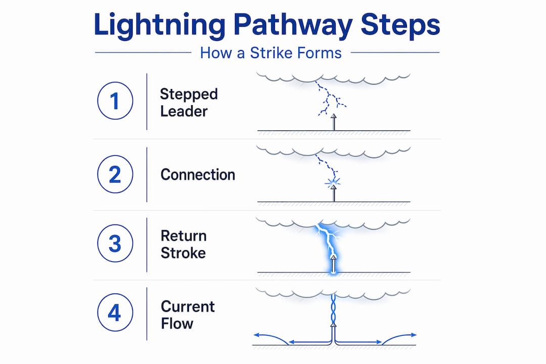
Charge separation in the thundercloud. Updrafts carry ice crystals upward while heavier graupel pellets descend. Their collisions transfer charge, leaving the lower cloud base strongly negative and the upper cloud region positive. Electric field strengths climb toward the megavolt-per-meter range.
Dielectric breakdown of air. Once the electric field exceeds roughly 3 MV/m locally, air molecules begin to ionize. Seed electrons, liberated by cosmic rays and natural radioactivity, trigger electron avalanches. Each avalanche ionizes more air, lowering resistance along that corridor.
Stepped leader propagation. The discharge does not flow continuously. Stepped leaders move in discrete jumps of approximately 50 to 100 meters, pausing for microseconds between each step. Each step follows the path of greatest local ionization, which varies chaotically with air density, humidity, and the presence of aerosols. The result is a branched, luminous plasma channel working its way downward.
Upward leader development from grounded structures. As the stepped leader approaches within a few hundred meters of ground, the intensified electric field beneath it triggers upward leaders from grounded objects including rooftops, trees, transmission towers, and air terminals. These upward streamers compete to connect with the descending channel.
Attachment and return stroke. When one upward leader meets the stepped leader, the circuit closes. A massive return stroke travels upward through the now-fully-ionized channel at speeds approaching one-third the speed of light. This is the visible flash. Peak currents commonly range from 20 kA to over 200 kA, lasting tens to hundreds of microseconds.
The branched geometry of a stepped leader is not a flaw in the physics. It is the direct result of competing ionization pathways, each probabilistically viable until one wins the race to attachment. No deterministic model predicts the exact channel geometry in advance.
This branching behavior is precisely why protection system design cannot rely on geometric shortest-path assumptions alone.
How lightning behavior shapes protection system design
Understanding how lightning channel formation works reframes several decisions you make at the drawing board. The channel that attaches to your structure is not necessarily the one that took the most direct route. It is the one whose upward leader formed earliest and most favorably, influenced by your structure’s geometry, height, and the conductivity of its surface and foundation.
Equipotential bonding as a pathway control mechanism
Equipotential bonding connects the lightning protection system, earthing system, and all significant conductive parts to a common reference potential. Its purpose is not merely compliance. During a strike, enormous transient currents flowing through down conductors create steep voltage gradients across any structure. Without bonding, a nearby grounded conductor, say a water pipe or cable tray, can sit at a potential several kilovolts different from the down conductor. That potential difference drives a side flash, which is an arc through air or through a person standing nearby.
Bonding does not eliminate the current. It controls where the current flows by offering a lower-impedance equalization path before a destructive arc forms spontaneously.
| Component | Function in the discharge pathway | Key design consideration |
|---|---|---|
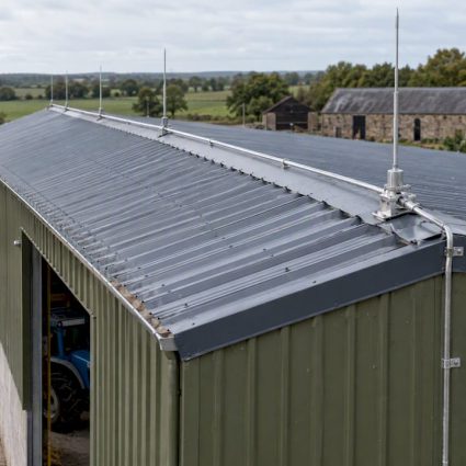
| Air terminal (lightning rod) | Initiates upward leader to intercept stepped leader | Placement height and coverage geometry per protection level |
| Down conductor | Carries strike current from terminal to earth | Routing, minimum bend radius, multiple parallel paths |
| Equipotential bonding bar | Equalizes potential between all bonded conductors | Bonding all metallic systems within structure perimeter |
| Earth termination system | Disperses current into soil | Soil resistivity, electrode geometry, grounding depth |
| Surge protection devices | Limits overvoltage on signal and power conductors | Coordination between SPD levels at service entrance and distribution |
Pro Tip:Verify resistance values at each bonding connection individually, not just at the earth electrode. A bond that reads correct at the electrode can mask a high-resistance joint two meters away on the bonding conductor.
For structures where architectural constraints limit down conductor routing, such as heritage facades or curtain-wall systems, review Indelec’s architecture-specific protection solutions for approaches that integrate pathway routing with structural and aesthetic requirements.
Implementation and testing in real projects
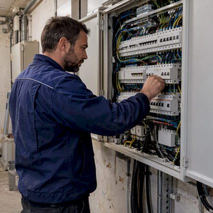
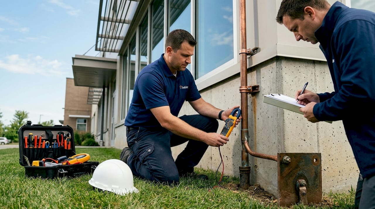
Getting the physics right on paper means nothing if the installed system deviates from design intent. Field practice introduces a specific set of failure modes that continuity-focused testing is designed to catch.
Conductor sizing and placement standards
DIN VDE 0100-540 specifies 6 mm² Cu as the minimum cross section for protective bonding conductors. For main bonding conductors connected directly to the lightning protection system, IEC 62305 series requirements typically drive larger cross sections, up to 16 mm² Cu or equivalent. Undersized conductors do not merely degrade performance. Under high-current strike conditions, they can fuse, open the pathway entirely, and redirect current through unintended routes including structural steel and conduit.
Testing methods that matter
- Continuity testing with high test current. Low test currents can mask contact resistance at corroded or mechanically loose joints. Use test currents above 200 mA to reveal resistances that a standard ohmmeter will miss.
- Reverse potential injection. This method drives current into the earth termination and measures return at bonding points throughout the structure, verifying that current distributes across the full mesh as designed.
- Holistic system evaluation. Single-route resistance checks miss parallel path interactions. Evaluate the full bonding mesh to confirm that no single failed joint compromises the overall current distribution.
- Visual inspection of mechanical connections. Corroded clamps, over-torqued connectors, and incompatible metal pairings create galvanic corrosion paths that degrade bonding integrity over years.
- Documentation against as-built drawings. Verify that installed conductor routing matches design, particularly after late-stage construction changes that commonly relocate conduit and structural steel.
Pro Tip:Treat your lightning protection system as a living document. Re-test after any structural renovation, addition of rooftop equipment, or change to the earthing topology. Strike pathways are sensitive to changes in the grounded geometry your system presents.
Poor continuity bonding negates the effectiveness of even a correctly designed down conductor layout. A loose clamp on a bonding strap is all it takes to redirect strike current through a path you never intended. For a broader look at lightning risk factors relevant to specific facility types, the assessment criteria vary significantly by structure height, occupancy, and equipment sensitivity.
Advances in understanding lightning initiation
The classical stepped-leader model explains most observable lightning behavior. But recent research is complicating the picture in ways that carry practical implications for protection system design margins.
- Cosmic rays and relativistic electron avalanches appear to contribute to lightning initiation by locally amplifying electric fields beyond what thundercloud charge separation alone can achieve. Gamma-ray bursts detected before lightning strikes support this interaction.
- Ice crystal geometry inside storm cells influences which regions of the cloud develop sufficient charge concentrations to generate stepped leaders, adding spatial variability that ground-based sensors cannot fully resolve.
- Exact attachment point prediction remains probabilistic. The physics of upward leader competition mean that even a perfectly designed air terminal does not guarantee 100% capture of every stepped leader that approaches it. Protection level ratings in IEC 62305 encode this probability explicitly.
- Lightning on Jupiter, where electrical storms on Jupiter have been observed by spacecraft, involves water and ammonia ice clouds operating under atmospheric pressures very different from Earth. Comparative planetology is helping researchers isolate which aspects of lightning initiation are universal and which are specific to Earth’s atmospheric chemistry.
- These findings collectively suggest that design safety margins in high-criticality installations, data centers, hospitals, and energy infrastructure, should account for pathway variability beyond what deterministic zone-of-protection calculations provide.
My perspective on what actually matters in the field
From nearly seven decades of working in lightning protection at Indelec, I’ve seen a consistent pattern: teams that invest in understanding lightning channel formation build better systems, not because they can predict exactly where a strike will attach, but because they design for the distribution of possible pathways rather than one idealized case.
The most common error I see is treating equipotential bonding as a compliance checkbox. It is the core mechanism through which you control current behavior inside a structure after attachment occurs. Getting the air terminal right matters. Getting the bonding wrong makes that air terminal irrelevant.
I’ve also watched projects fail to account for pathway changes introduced by late-stage design modifications. A steel column added to a facade, a rooftop HVAC unit bolted to structural steel without bonding, these are the changes that create unintended current pathways. The physics do not care about project phases.
My recommendation: integrate lightning protection coordination into the design process from concept, not as a retrofit. Every structural and facade decision affects the pathway geometry your system must manage. And commit to post-construction testing that goes beyond visual inspection. The gap between a system that looks correct and one that performs correctly is measured in continuity tests, not certificates of completion.
— Indelec
How Indelec supports your lightning protection projects

Translating lightning pathway physics into a compliant, field-verified protection system requires the right hardware and the right expertise. Indelec’s Prevectron3 air terminal, featuring OptiMax technology, is engineered to maximize upward leader formation ahead of competing attachment points, giving your protection zone the physical basis the design assumes. Beyond the air terminal, Indelec provides technical consulting, system design review, and installation support aligned with IEC 62305 and applicable national standards. For projects requiring a full assessment of your protection system design and pathway coordination, Indelec’s engineering team brings the depth of experience to identify gaps before a strike reveals them. Reach out to discuss your project requirements.
FAQ
What is a stepped leader in lightning channel formation?
A stepped leader is the initial ionized plasma channel that extends downward from a thundercloud in discrete jumps of roughly 50 to 100 meters. It guides the eventual high-current return stroke to ground once it connects with an upward leader from a grounded structure.
Why doesn’t lightning always strike the tallest object nearby?
Lightning attaches to the grounded object whose upward leader connects first with the descending stepped leader, which depends on local electric field geometry, surface conductivity, and timing. Height increases the probability of connection but does not guarantee it for every strike.
What does equipotential bonding prevent during a lightning strike?
Equipotential bonding limits the potential difference between conductive systems inside a structure during a strike. Without it, steep voltage gradients along the current pathway drive side flashes between conductors, which can cause fires, equipment damage, and electric shock hazards.
How do I verify my lightning protection pathway is performing correctly?
Use continuity testing with test currents above 200 mA at each bonding connection, supplement with reverse potential injection across the earthing mesh, and compare results against as-built documentation. Visual inspection alone is insufficient to confirm pathway integrity.
What standards govern conductor sizing for lightning protection pathways?
IEC 62305 governs the overall lightning protection system design, including down conductor specifications. DIN VDE 0100-540 specifies minimum cross sections for protective bonding conductors, with 6 mm² Cu as a baseline that specific protection levels and installation conditions can exceed.