Asset Mapping for Lightning Safety: A Facility Manager’s Guide

TL;DR:
- Effective lightning asset mapping converts invisible hazards into documented protection systems, preventing equipment damage and injuries. It involves thorough site surveys, applying standards like IEC 62305 and NFPA 780, and maintaining accurate, updated records of all grounding, surge protective devices, and protection zones. Organization, routine updates, and integrated change management are vital to ensure the map remains reliable over time.
Lightning is not an abstract risk. For industrial and commercial facilities, a single undetected vulnerability in your protection network can mean equipment destruction, regulatory violations, and worker injuries. Effective asset mapping for lightning safety turns an invisible hazard into a documented, manageable system. This guide gives you the structured approach to identify every at-risk asset, apply the right protection standards, and build an audit-ready record that holds up under inspection and incident review.
Table of Contents
- Key takeaways
- Planning before you map
- How to conduct asset mapping for lightning safety
- Common mistakes that undermine your asset map
- Verifying and maintaining your asset maps
- My perspective on where asset mapping programs actually break down
- How Indelec supports your lightning safety program
- FAQ
Key takeaways
| Point | Details |
|---|---|
| Start with documentation | Collect blueprints, equipment inventories, and site plans before any physical survey begins. |
| Apply standards from the start | IEC 62305 and NFPA 780 determine your protection levels and drive every mapping decision. |
| Use the Rolling Sphere Method | This method defines protection zones for air terminal placement across all asset types. |
| Map SPDs and grounding precisely | Surge protective device locations and single-point bonding must be explicitly documented. |
| Update maps after every change | Facility expansions, repairs, and storm events each require a corresponding map revision. |
Planning before you map
Most asset mapping programs fail before the first site walk because the preparatory work was skipped or compressed. You need three categories of documentation assembled before any survey begins: structural drawings (including roof plans and elevation views), electrical schematics showing panel locations and feeder paths, and a current equipment inventory that includes sensitive electronics, PLCs, and instrumentation.
Standards compliance is not optional. IEC 62305 and NFPA 780 frame the entire mapping exercise. IEC 62305 uses a risk assessment model factoring in lightning flash density, occupancy type, environmental exposure, and equipment sensitivity to assign Protection Levels I through IV. NFPA 780 takes a more prescriptive route. Combining both gives you an approach that is both risk-calibrated and prescriptively defensible.
Your team setup matters as much as your documentation. Assign clear roles before fieldwork starts:
- Survey lead: Responsible for physical asset identification and zone marking
- Electrical specialist: Validates grounding topology and SPD locations
- Documentation coordinator: Maintains version control on all drawings and test records
- Safety officer: Confirms compliance with site-specific protocols and applicable standards
Software selection also happens at this stage. GIS-based tools handle geospatial asset correlation well for large outdoor sites. CAD-based schematics work better for indoor electrical documentation. Many mature programs use both in parallel.
Pro Tip:Before your first site visit, cross-reference your equipment inventory against your insurer’s asset register. Discrepancies often reveal undocumented additions that have never been assessed for lightning exposure.
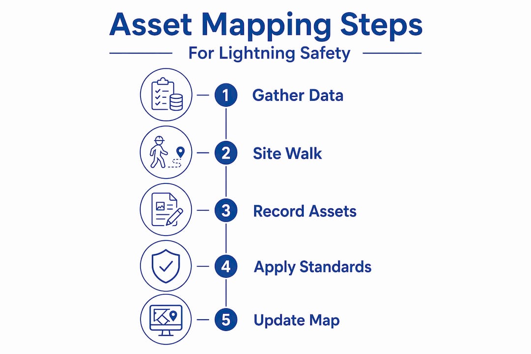
How to conduct asset mapping for lightning safety
This is where lightning risk mapping becomes concrete. Follow this sequence to ensure nothing critical gets missed.
Conduct a physical site survey. Walk every exterior elevation, rooftop, and subterranean entry point. Identify all metallic structures, antennas, HVAC units, elevated tanks, and cabling pathways. Mark each on your base drawing with GPS coordinates or grid references.
Apply the Rolling Sphere Method to determine protection zones. The Rolling Sphere Method uses class-based radii: 20 meters for Class I, 30 meters for Class II, 45 meters for Class III, and 60 meters for Class IV. Roll the virtual sphere across your site model. Any point the sphere touches is a potential strike attachment point and requires an air terminal.
Address tall structure exceptions explicitly. Buildings taller than the sphere radius present a gap that the standard rolling sphere analysis will not catch on its own. For Protection Level I, structures above 20 meters require discrete protection on the upper 20% of the vertical facade. Mark these zones separately on your elevation drawings.
Map grounding and bonding systems. Trace every down conductor path and confirm connection to the earth termination network. Mark all bonding conductors connecting metallic structures, pipes, and cable trays. Single-point bonding is the standard requirement. Equipment grounds and lightning protection grounds must tie together at one location to prevent circulating surge currents through sensitive equipment.
Document every SPD location. Map each surge protective device by panel, circuit, and physical location. For high mast or stadium lighting, cabinet-only SPD placement is insufficient. Coordinated placement at both the cabinet and the luminaire level, with verified grounding, is required.
Correlate digital assets with physical locations. Use your GIS or CAD tool to link each documented asset to its schematic representation. This correlation is what makes emergency response mapping useful. A technician responding to a post-storm fault should be able to open one file and find the physical location, the protection zone, and the grounding path for any affected asset.
The table below summarizes key parameters for common asset types encountered during a facility survey:
| Asset type | Key mapping data to capture | Applicable standard reference |
|---|---|---|
| Air terminals (lightning rods) | Position, height, protection radius, class | IEC 62305, NFPA 780 |
| Down conductors | Route, material, cross-section, bonding points | IEC 62305 Part 3 |
| Earth termination system | Electrode type, resistance value, bonding bus location | IEC 62305, NFPA 780 |
| Surge protective devices | Panel ID, circuit, rating, grounding path | IEC 62305 Part 4 |
| Tall structures (upper facade) | Facade height, 20% zone boundary, discrete terminal locations | IEC 62305 Part 3 |
| High mast lighting | Pole height, SPD at cabinet and luminaire, grounding design | SPD specification standards |
Pro Tip:When applying the Rolling Sphere Method to outdoor substations, use both plan view and elevation view analyses. Substation lightning shielding typically uses a 40-meter sphere radius for a 10kA design stroke. Skipping the elevation view leaves equipment in shadow zones undetected.
Common mistakes that undermine your asset map
Even well-resourced programs make avoidable errors. Knowing where other facilities get it wrong is the fastest way to protect your own program.
Treating bonding as an afterthought. The most damaging mistakes in lightning hazard identification involve grounding topology. When equipment grounds and lightning protection grounds connect at multiple points rather than one, surge currents circulate through instrumentation and PLCs. This is not a marginal risk. Industry standards require a single integrated earth termination system specifically to prevent this failure mode.
Missing the upper facade on tall assets. The rolling sphere model’s geometry means the top portion of tall structures falls outside the sphere’s reach. Many mappers stop at rooftop level and miss the lateral exposure on upper elevations. This is a documented limitation of the method, not a judgment call.
Using static maps that go stale. A map created at facility commissioning and never updated is worse than no map. It creates false confidence. Every expansion, equipment addition, or significant storm event must trigger a map update.
Inadequate SPD documentation. Clear as-built records for SPD placement and grounding are what allow technicians to replace the right device after a surge event. Without them, replacement becomes guesswork, and the next surge finds the same gap.
No photographic evidence in the record. Written descriptions of terminal locations and conductor paths are ambiguous. Photos tied to asset IDs create an unambiguous audit trail.
Field reality check: A facility that experiences recurring SPD failures after storms almost always has one of two underlying issues: a missing or incorrect bonding connection, or an SPD rated for the wrong exposure level. Neither problem is visible without a detailed, current asset map to compare against.
Verifying and maintaining your asset maps
Documentation is only as good as its accuracy at the moment you need it. Verification and maintenance are the disciplines that keep your lightning protection maintenance workflow from degrading over time.
Conduct continuity and ground resistance testing after initial mapping. Every down conductor path needs a continuity check. Every earth termination electrode needs a measured resistance value recorded against your map. These baseline numbers are your reference for future testing cycles.
Schedule periodic inspections tied to storm seasons. Post-storm inspections should follow any significant lightning event affecting your site. Mapping storm history to repeat faults lets you narrow inspection scope significantly. Rather than walking the entire facility, your team can target the assets with documented exposure history.
Build an audit trail with photographic and documentary evidence. Every inspection should add to the record. Date-stamped photos, test results, and sign-off sheets attached to specific asset IDs create the traceability insurers and regulators expect.
Update maps immediately after facility changes. New rooftop equipment, added HVAC units, structural modifications, and cabling changes all affect your protection zones. A change management protocol that routes facility modifications through the safety officer’s review before implementation prevents gaps from forming silently.
Coordinate updates across teams. Maintenance technicians, electrical contractors, and safety officers each hold information the others need. A shared, version-controlled digital asset map is the mechanism that keeps those information streams connected.
Pro Tip:Build your map update trigger into your facility change management form. When any modification to structural, electrical, or mechanical systems requires sign-off, add a checkbox that asks: “Does this change affect lightning protection zones or grounding paths?” This takes three seconds per form and prevents months of undetected gaps.
My perspective on where asset mapping programs actually break down

In my experience working with industrial facilities across a wide range of sectors, the gap between a functional asset map and an ineffective one almost never comes down to technical knowledge. It comes down to organizational discipline.
I’ve seen facilities with excellent initial documentation that became liabilities within three years because no one owned the update process. The drawings reflected the facility as it was built, not as it stood. When a storm exposed a fault, the map pointed to protection that no longer existed.
What I’ve found actually works is treating the asset map as a living system, not a project deliverable. The most effective programs I’ve encountered tie map updates to the change management workflow, not to a separate annual review that invariably gets deprioritized. When the map update is embedded in the same process as the facility modification, it happens automatically.
The other thing I’d push back on is the industry tendency to underestimate bonding complexity. Single-point bonding sounds simple in a standard. In practice, across a large facility with decades of piecemeal additions, finding every parallel grounding path and eliminating it requires a methodical survey and someone who understands why it matters. Predictive, asset-correlated detection strategies are making this easier by flagging which assets absorb repeat faults. But the map still has to be accurate for those signals to mean anything.
Facilities that combine IEC 62305 risk assessment with NFPA 780 prescriptive standards consistently outperform those that rely on a single framework. The risk-based approach identifies where protection is truly critical. The prescriptive approach ensures the minimum baseline is never missed.
— Indelec
How Indelec supports your lightning safety program
Indelec has been engineering lightning protection systems since 1955, and asset mapping sits at the center of every protection program we deliver. Whether you are commissioning a new facility or auditing an existing one, our team brings the technical depth to translate your site survey into a standards-compliant, audit-ready protection design.
Our lightning protection services cover risk assessment, system design, installation, and certification. For facility managers working through IEC 62305 or NFPA 780 compliance, our lightning standards resource center provides the regulatory clarity that makes compliant mapping achievable. If you are ready to translate your asset map into a protection system, explore our lightning protection system applications designed specifically for industrial and commercial infrastructure.
FAQ
What is asset mapping for lightning safety?
Asset mapping for lightning safety is the process of systematically identifying, documenting, and spatially recording all assets that require protection from lightning strikes, including air terminals, grounding systems, down conductors, and surge protective devices. The resulting map drives both protection design and ongoing maintenance decisions.
Which standards govern lightning protection asset mapping?
IEC 62305 and NFPA 780 are the primary standards. IEC 62305 uses a risk-based Protection Level system (I through IV), while NFPA 780 prescribes specific installation requirements. Using both together produces a protection program that is risk-calibrated and prescriptively compliant.
How does the Rolling Sphere Method apply to asset mapping?
The Rolling Sphere Method determines which points on a structure or site are exposed to lightning attachment. By applying class-specific sphere radii (20 to 60 meters depending on protection level), facility managers can identify where air terminals must be placed and which assets fall within protected zones.
How often should lightning safety asset maps be updated?
Asset maps should be updated after any structural or electrical modification to the facility, after any significant lightning event, and at minimum during each scheduled annual inspection. Waiting for a single annual review creates gaps that storms and auditors will find first.
Why does single-point bonding matter in asset mapping?
Single-point bonding prevents surge currents from circulating through equipment grounds and sensitive electronics. When an asset map fails to document and verify this single connection point, post-strike equipment damage, particularly to PLCs and instrumentation, becomes predictable rather than accidental.