Lightning current distribution: keep your facility safe

TL;DR:
- Steel structures carry approximately 80% of lightning current due to low impedance pathways.
- Lightning current favors existing metallic paths like rebar and structural steel over dedicated conductors.
- Effective protection requires deliberate bonding of steel, rebars, and metallic infrastructure into the lightning protection system.
Most facility managers assume their installed lightning conductors handle the bulk of any strike current. That assumption is dangerously wrong. Empirical measurements in steel frame buildings show the structural skeleton carries roughly 80% of lightning current, while the dedicated conductor grid takes only about 20%, simply because steel offers a lower impedance path. Understanding how current actually moves through your building is the first step toward a protection strategy that works in the real world, not just on paper.
Table of Contents
- Why lightning current distribution matters for facility safety
- How lightning currents actually travel: Evidence from real buildings
- Critical factors influencing current distribution
- Design guidelines for effective lightning current distribution
- A critical perspective: What most guides miss about lightning current distribution
- Need help protecting your facility? Industry-leading solutions for lightning current safety
- Frequently asked questions
Key Takeaways
| Point | Details |
|---|---|
| Structure dominates current flow | Steel frames and rebars carry most of the lightning current, not just dedicated conductors. |
| Impedance shapes distribution | Currents follow the lowest impedance, causing uneven sharing across different paths. |
| Model complex systems | Simulations are often necessary for non-uniform or modern buildings to ensure safety. |
| Standards and bonding are essential | Intentional bonding and compliance with standards protect against hidden risks. |
Why lightning current distribution matters for facility safety
Lightning is not a well-behaved phenomenon. When a strike hits your facility, the resulting current does not politely follow the conductors your engineer specified at design time. It finds the fastest, lowest-resistance route available. In most modern industrial or commercial buildings, that means the steel frame, the reinforced concrete columns, and every metallic utility run within the structure will carry significant current whether you planned for it or not.
This matters because unmanaged current paths create predictable and serious problems:
- Fire ignition at points where uncontrolled current arcs across gaps between metallic components
- Equipment damage and downtime as surge energy couples into electrical, data, and control systems
- Touch and step voltage hazards that expose workers to shock risk even when they are not near the strike point
- Structural damage at connection points where local heating from high currents degrades welds, concrete, or insulation
- Compliance exposure when auditors find bonding gaps or undocumented current paths
Consider a large manufacturing plant with overhead cranes and a programmable logic controller network. A single poorly managed strike can weld crane rail joints, corrupt PLC programs, and knock out cooling systems simultaneously. The downtime cost alone can easily outpace years of proper protection investment.
Statistic callout: Insurance industry data consistently places lightning among the top five causes of industrial fire claims, with average losses per event running well above general property claims due to cascading equipment damage.
The regulatory picture reinforces urgency. OSHA expects facilities to demonstrate active risk management for atmospheric electrical hazards, and insurers increasingly require documented lightning protection assessments as a condition of coverage in high-risk sectors like petrochemical, pharmaceutical manufacturing, and data center operations. Gaps in infrastructure lightning protection are no longer issues you can defer without financial and legal consequence.
Pro Tip: Walk your facility with your maintenance team and identify every large metallic mass, including steel columns, cable trays, ductwork, and tank supports. Any of these can become an unintended current path during a strike. Documenting them now is the first step toward deliberate bonding.
Because steel structures dominate current flow, the safest and most effective strategy integrates structural members into the protection design through deliberate bonding rather than treating them as passive bystanders to your conductor network.
How lightning currents actually travel: Evidence from real buildings
Intuition says that if you install a properly designed lightning protection network, current will flow through it. Research says otherwise. The behavior of lightning current in real structures is governed by physics, specifically impedance, not by design intent.
A well-documented study using a controlled 0.3 kA current injection into a steel frame building produced results that should recalibrate how every facility manager thinks about their protection system. The steel skeleton carried 80% of the injected current, leaving the purpose-built lightning conductor grid to handle only the remaining 20%. The reason is straightforward: steel columns and beams form a dense, interconnected network with very low inductive impedance, and lightning current, like all electrical current, favors the path of least resistance.
| Current path | Percentage of total current | Primary reason |
|---|---|---|
| Structural steel skeleton | ~80% | Low inductive impedance, dense connectivity |
| Dedicated lightning conductors | ~20% | Higher impedance relative to steel mass |
| Reinforced concrete rebars | Variable | Acts as natural down conductors when bonded |
| Unintended metallic paths | Unpredictable | Cable trays, pipes, ductwork |
This table is not an abstraction. It reflects actual paths that deviate significantly from what most protection designs assume. The practical consequence is that if you design your bonding and grounding strategy around the assumption that 100% of current flows through your conductors, you are leaving 80% of the actual current flow unaccounted for.
“The building structure is not a passive shell surrounding a lightning protection system. It is an active participant in current flow, and it will behave that way whether or not your design acknowledges it.”
This insight reframes the entire design problem. Facility managers working on lightning protection applications need to think of the structural frame as the primary conductor and design bonding connections accordingly. The dedicated conductor network becomes a supplement and control mechanism rather than the primary carrier.
Pro Tip: When reviewing protection drawings, check whether the design explicitly accounts for current in structural steel. If the bonding schedule only references conductor-to-ground connections and ignores column-to-conductor bonds, your design has a significant gap.
For a practical walkthrough of how to apply this thinking from the ground up, reviewing a step-by-step lightning protection framework for infrastructure projects will show you how leading practitioners translate this evidence into installation practice.
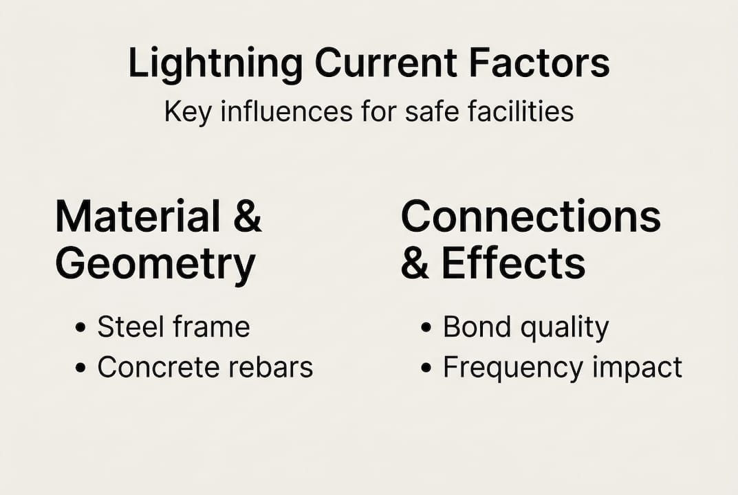
Critical factors influencing current distribution
Knowing that steel dominates is useful. Knowing why it dominates in specific configurations and how other variables shift the balance is what allows you to design smarter protection. Several factors drive the actual distribution outcome at any given facility.
Material type and geometry
Steel has excellent electrical conductivity and, in a frame building, forms a three-dimensional mesh with many parallel current paths. Reinforced concrete works differently. The rebars embedded in concrete columns and slabs act as natural down conductors, providing low-impedance routes that can rival or exceed the capacity of external conductors. In facilities where reinforced concrete is the primary structural material, understanding rebar connectivity becomes critical because current will concentrate in the densest, most continuous rebar networks.

Inductive impedance and frequency effects
Lightning current is not a slow DC signal. It rises in microseconds, meaning the high-frequency components of the waveform drive behavior. At high frequencies, inductive impedance dominates over DC resistance. Two parallel cables of identical length and cross-section will not share current equally because small differences in loop area and routing geometry create measurable impedance differences. Parallel cable imbalances of 10 to 20% are common even in well-installed systems, which means relying on assumed equal sharing between conductors is an engineering error.
Bonding quality and connection points
A bond that looks correct on a drawing but has a corroded joint or an undersized clamp will have elevated impedance. Current will route around it. Over time, especially in humid or corrosive industrial environments, bonding connections degrade without visible signs. Regular inspection protocols that verify actual connection quality, not just presence, are essential.
| Factor | Effect on distribution | Mitigation approach |
|---|---|---|
| Steel frame density | Concentrates 80%+ of current | Deliberate bonding to protection network |
| Rebar continuity | Creates parallel down conductor paths | Map and bond rebar at design stage |
| Cable routing geometry | Causes 10-20% imbalance in parallel runs | Use FEM modeling for complex layouts |
| Connection corrosion | Increases local impedance, redirects current | Annual inspection and torque verification |
| Building irregularity | Creates unpredictable hot spots | Simulation required for non-standard structures |
When simulation becomes necessary
For rectangular, structurally regular buildings, experienced engineers can reason through distribution with established formulas. For facilities with non-uniform distribution challenges, including irregular floor plates, mixed construction materials, partially embedded steel, or large equipment masses inside the structure, finite element method (FEM) modeling provides the only reliable path to accurate current distribution analysis. The software processes the full three-dimensional geometry and material properties to predict where current will flow and where hotspots might occur.
Pro Tip: If your facility has undergone any major renovation, equipment addition, or structural modification since its lightning protection was last assessed, treat it as a new analysis problem. The current paths you assumed may no longer exist, and new unintended paths may have been introduced.
Facilities classified as highly sensitive sites, such as hospitals, data centers, and explosive materials storage, should commission FEM analysis as a standard part of every protection review cycle. For general industrial facilities, simulation at least once per major modification cycle represents a reasonable and defensible practice standard.
For broader context on how construction type affects protection requirements, reviewing guidance on facility lightning safety helps frame the full scope of a robust assessment program.
Design guidelines for effective lightning current distribution
With the physics understood and the key variables mapped, the practical question becomes: what should you actually do? Here is a structured approach that reflects current best practice for facility managers responsible for real buildings.
Audit all current paths, not just designed conductors. Walk every floor, roof level, and basement. Identify all metallic structures, cable trays, pipes, ductwork, crane rails, and equipment frames. Document their connectivity. You cannot manage current paths you have not identified.
Bond structural steel deliberately to the protection network. Every major steel column should have a verified, low-impedance connection to the down-conductor network and ultimately to the grounding system. Connections should be sized for the expected current share, which as we have established is the majority of strike current, not a residual fraction.
Integrate rebars in reinforced concrete structures. Where rebars are continuous and well-connected, bond them at the foundation level and at roof level to the equipotential bonding network. This converts an uncontrolled path into a managed one.
Supplement with dedicated conductors where structural paths are insufficient. Areas of the building with limited structural steel, such as lightweight roof structures, modular additions, or equipment enclosures, need supplemental conductors to ensure adequate current handling.
Commission FEM modeling for complex or irregular structures. As noted in current research, simulations are needed for non-uniform layouts where analytical methods cannot reliably predict distribution. This is not optional for high-risk or highly sensitive facilities.
Verify compliance with applicable standards. Your design and installation must align with IEC 62305, NFPA 780, or the relevant national standard for your jurisdiction. These standards set minimum requirements for conductor sizing, spacing, bonding, and testing.
“Compliance with the letter of a standard is the floor, not the ceiling. A building that meets minimum requirements may still have unmanaged current paths if the design did not account for actual structural current flow.”
- Schedule regular verification testing. Grounding resistance measurements, bonding continuity checks, and visual inspection of all connections should occur on a defined cycle, typically annually for industrial facilities and after any significant weather event or structural modification.
Reviewing the applicable lightning protection standards for your region and sector ensures your protection program rests on a defensible technical and regulatory foundation. For a workflow that maps these steps into a practical project sequence, the protection planning steps resource provides a structured framework suited to industrial and commercial contexts.
A critical perspective: What most guides miss about lightning current distribution
Most lightning protection checklists focus on adding conductors. Count the down conductors, check the spacing, verify the ground resistance, and sign off. This approach has a fundamental flaw: it treats the building as a passive background and the protection system as the active element. The evidence shows the opposite is true.
The single most overlooked principle in facility lightning safety is that the building is the primary conductor. Every major steel element, every continuous rebar run, every large metallic mass is already carrying current during a strike, regardless of whether your design acknowledges it. Failing to deliberately bond these elements into a controlled network is not a conservative position. It is an active decision to leave the majority of current flow unmanaged.
We have also seen facilities invest heavily in advanced air terminals while leaving structural bonding incomplete. The air terminal captures the strike. The bonding network determines where the resulting current goes. Prioritizing capture over distribution is like installing a high-capacity valve on a pipe with open joints.
The nuance that saves budgets and lives is this: every building is structurally unique. The 80/20 split documented in research is an average, not a constant. Your facility’s actual distribution depends on its specific geometry, materials, and connectivity. That is why empirical testing and simulation matter so much. Generic rules of thumb, applied without site-specific analysis, give you false confidence.
Our work across industrial and infrastructure sectors shows that the facilities with the strongest protection outcomes are the ones that treat their building structure as an engineering resource for electrical safety, not a complication to work around. Bond it, model it, test it, and verify it. That approach consistently outperforms adding conductors alone.
Need help protecting your facility? Industry-leading solutions for lightning current safety
Understanding current distribution is one thing. Implementing a system that accounts for real-world behavior requires proven technology, engineering expertise, and ongoing support.

Indelec has been designing and installing advanced lightning protection systems since 1955, with solutions deployed across industrial plants, data centers, petrochemical facilities, and critical infrastructure worldwide. Our Prevectron3 air terminal delivers early streamer emission technology backed by decades of field performance and third-party validation, and our lightning protection system application portfolio covers the full range of industrial and commercial protection needs. For facilities evaluating performance against traditional rods, independent research confirming the higher efficiency of ESE lightning rods provides a useful technical reference. Contact our engineering team to schedule a site assessment.
Frequently asked questions
What percentage of lightning current does a building’s steel skeleton typically carry?
Empirical studies show the steel skeleton often carries about 80% of the current, with the dedicated lightning grid taking only about 20%, due to the lower inductive impedance of the structural steel mass.
Why can’t we assume lightning currents are equally distributed among conductors?
Inductive impedances cause imbalance of 10 to 20% even among parallel conductors of identical length, because small differences in routing geometry affect high-frequency impedance and shift current sharing unpredictably.
What role do rebars in reinforced concrete play in lightning current distribution?
Rebars act as natural down conductors within concrete structures, providing dense, low-impedance paths for lightning current that can carry significant portions of total strike energy when they are continuous and properly bonded.
How can facility managers ensure effective lightning current distribution?
Managers should bond structural steel and rebars deliberately into the protection network, supplement with dedicated conductors where needed, and commission simulations for non-uniform or complex layouts to identify and control all significant current paths.