Why High Voltage Substations Need Protection
TL;DR:
- High voltage substation protection involves equipment and protocols that detect and isolate faults instantly to prevent damage and outages. Proper grounding, fast relay schemes, and intelligent monitoring are essential to safeguard assets and personnel effectively. Regular maintenance, testing, and adherence to safety standards ensure long-term reliability and safety of substation systems.
High voltage substation protection is the system of equipment and protocols designed to instantly detect and isolate electrical faults to prevent equipment damage and widespread outages. Understanding why high voltage substations need protection is not optional for electrical engineers, safety officers, or facility managers. It is the foundation of every reliable grid operation. Standards from IEEE, OSHA, and NFPA 70E define the minimum requirements, and the consequences of ignoring them range from transformer destruction to fatal personnel accidents. Substation protection systems work across three layers: fault detection, physical safety, and environmental hazard control, including lightning.
What are the main faults and risks that threaten high voltage substations?
High voltage substations face a defined set of electrical fault types, each capable of causing catastrophic damage if not isolated within milliseconds. Short circuits, earth faults, and sustained overloads are the most common. Each one forces abnormal current through conductors and equipment not rated to handle it.
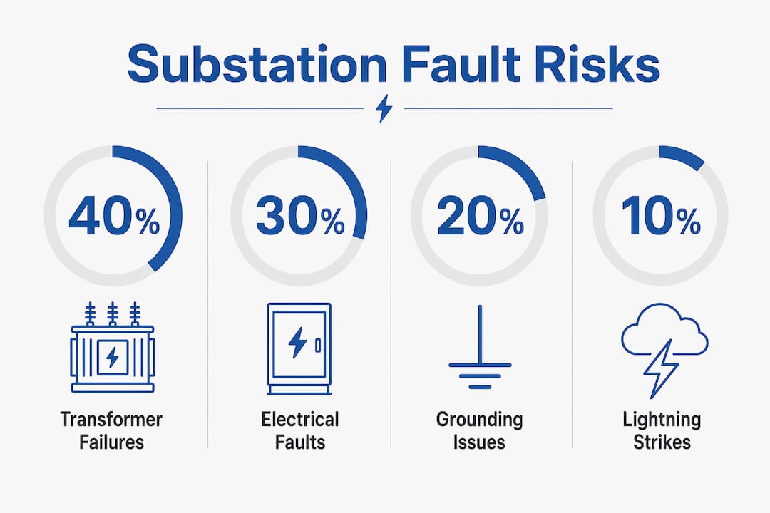
Short circuits produce current surges that can physically destroy busbars, insulators, and switchgear. Earth faults redirect current through unintended paths, including structural steel and soil, creating lethal touch and step potentials for anyone nearby. Overloads generate heat that degrades insulation over time, eventually causing failures that look sudden but were building for months.
Physical and environmental threats compound these electrical risks:
- Lightning strikes inject high-energy transients directly into substation equipment, damaging transformers, surge arresters, and control systems.
- Extreme weather accelerates insulator contamination, which lowers flashover voltage and increases fault probability.
- Vegetation encroachment creates phase-to-ground faults on overhead lines feeding the substation.
- Equipment aging raises the probability of insulation breakdown, especially in transformers operating beyond their design life.
Power transformers are the most valuable substation assets, and a single transformer failure can cause months of downtime with financial losses that dwarf the cost of any protection system. That fact alone justifies the full investment in substation protection systems.
How do protective relays and control schemes safeguard substations?
Protective relays are the detection and decision layer of every substation protection scheme. They continuously measure electrical quantities, including current, voltage, frequency, and impedance, and compare them against set thresholds. When a measurement crosses a threshold, the relay sends a trip signal to the circuit breaker, isolating the faulted section in milliseconds.
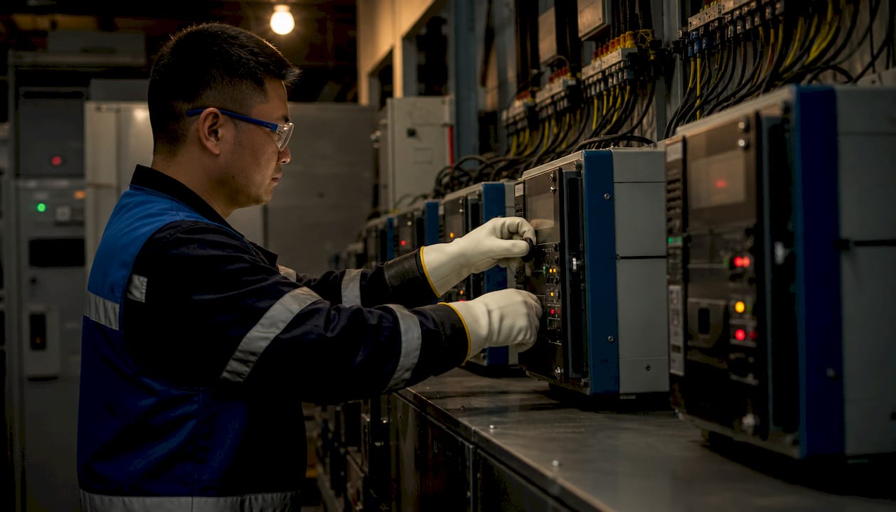
Protective relays preserve equipment and ensure operational continuity by isolating faults before they cascade. A well-coordinated relay scheme localizes the fault to the smallest possible section of the network, keeping the rest of the grid energized. That selectivity is what separates a brief interruption from a regional blackout.
Speed is the single most critical performance parameter. Clearing faults within 0.5 seconds versus 1 second is the difference between minor equipment stress and catastrophic, permanent failure. Faster clearance protects multimillion-dollar assets that cannot be replaced quickly.
Effective relay protection follows four core principles:
- Speed: Minimize fault duration to limit energy released at the fault point.
- Selectivity: Trip only the breakers necessary to isolate the fault, preserving the rest of the network.
- Redundancy: Provide a backup relay and trip path in case the primary system fails.
- Security: Avoid unnecessary trips. Protection schemes must balance redundancy and security, since duplicating certain functions can cause harmful, unnecessary tripping.
Protection sub-systems are kept autonomous to prevent inter-system faults. Dual trip coils are standard practice because a trip circuit failure disables the ability to open a breaker, even when the relay correctly detects a fault. Redundancy at the trip coil level costs far less than a failed breaker during a fault event.
Pro Tip:When commissioning a new relay scheme, always perform end-to-end injection testing that simulates actual fault conditions. Functional testing of the relay alone does not verify the complete trip path from relay output to breaker coil.
Why is grounding critical in substation protection and safety?
Grounding is a life-safety system, not a passive design element. Fault events deliver tens of kiloamperes in milliseconds, and the ground grid provides the low-resistance path that keeps that current away from personnel and structures. Without a properly designed earthing grid, fault current seeks any available path, including a technician’s body.
The ground grid achieves safety through two mechanisms: equipotential bonding and surface resistivity control. Equipotential bonding connects all metallic structures to a common reference, eliminating dangerous voltage differences between adjacent objects. Surface resistivity control uses a layer of crushed aggregate rock to increase the resistance between a person’s feet and the earth, limiting the current that can flow through the body during a ground potential rise event.
Key grounding design and maintenance requirements include:
- Grid design per IEEE Std. 80: Calculate touch and step voltages for the maximum fault current and verify they stay within safe limits.
- Aggregate surface layer: Maintain a 2–6 inch layer of crushed rock. Grounding aggregate increases surface resistivity, critically reducing hazardous touch and step potentials. It is not decorative.
- Periodic resistivity testing: Retest aggregate resistivity every 5 years per IEEE Std. 81-2025. Contamination, compaction, and erosion degrade effectiveness over time.
- Ground potential rise analysis: Evaluate GPR for all fault scenarios to identify alternative current paths that could energize adjacent structures or communication cables.
| Grounding parameter | Requirement |
|---|---|
| Aggregate layer depth | 2–6 inches of crushed rock |
| Resistivity retest interval | Every 5 years per IEEE Std. 81-2025 |
| Design standard | IEEE Std. 80 for touch and step voltage |
| Bonding scope | All metallic structures within the substation fence |
Pro Tip:After any significant excavation or civil work inside the substation fence, retest the ground grid resistance immediately. Construction activity frequently damages buried conductors without any visible surface indication.
Indelec’s deep earth grounding drilling service addresses sites where surface soil resistivity is too high for a conventional grid to achieve safe ground resistance values. Drilling to lower soil strata with higher moisture content provides a reliable low-resistance path regardless of surface conditions.
What are the key safety protocols for working in high voltage substations?
Personnel safety in substations depends on procedural discipline as much as engineering design. OSHA and NFPA 70E mandate that only qualified persons perform energized substation maintenance, using Lockout/Tagout procedures with voltage tester verification before any contact with equipment. Qualification is not a title. It requires formal training, demonstrated competency, and documented authorization.
The core safety protocols every facility manager must enforce include:
- Lockout/Tagout (LOTO): De-energize, isolate, lock, and verify zero energy before any maintenance work begins. Voltage tester verification is mandatory, not optional.
- Two-person rule: High-risk tasks require a second qualified person present. One person works; the other observes and is prepared to respond to an emergency.
- Arc flash hazard analysis: Calculate incident energy for every work location per NFPA 70E. Post arc flash labels on all equipment panels with required PPE categories.
- Personal protective equipment: Arc-rated clothing, face shields, insulating gloves rated for the voltage class, and dielectric footwear are the minimum for energized work.
- Approach boundaries: Enforce limited approach and restricted approach boundaries for both qualified and unqualified workers near energized conductors.
Reviewing electrical protection standards before planning any maintenance outage helps safety officers confirm that local procedures align with current regulatory requirements. Standards update regularly, and a procedure written three years ago may no longer meet the current NFPA 70E edition.
How do intelligent monitoring systems improve substation reliability?
Traditional substation monitoring relies on single-source data, typically one sensor type per asset. That approach creates blind spots because a single sensor cannot distinguish between a real fault signature and noise from an adjacent system. The result is either missed early warnings or excessive false alarms that erode operator trust.
Intelligent substation monitoring uses multi-source data fusion, combining electrical measurements, thermal imaging, acoustic sensors, and partial discharge detectors into a single analytical layer. Advanced multi-source data fusion methods improve monitoring accuracy by 20%, reduce false alarms by 30%, and increase early warning lead times by 20%. Those gains translate directly into fewer unplanned outages and longer asset life.
| Monitoring approach | Fault detection accuracy | False alarm rate | Early warning lead time |
|---|---|---|---|
| Traditional single-source | Baseline | Higher | Shorter |
| Intelligent multi-source fusion | +20% improvement | 30% reduction | 20% longer |
A 2026 study on homologous recording methods recorded a 30% reduction in fault response time and a 25% improvement in overall operational efficiency compared to traditional monitoring. That efficiency gain matters most for substations operating in regions where replacement parts have long lead times and every hour of downtime carries significant cost.
The practical implication for facility managers is clear. Upgrading monitoring infrastructure is not a capital expense that competes with protection hardware. It is the layer that makes protection hardware perform at its rated capability by giving operators accurate, timely information before a fault forces a trip.
Key Takeaways
High voltage substations require layered protection because no single system addresses every fault type, physical hazard, and personnel safety risk simultaneously.
| Point | Details |
|---|---|
| Fault isolation speed | Clearing faults in 0.5 seconds versus 1 second prevents catastrophic transformer failure. |
| Relay scheme design | Speed, selectivity, redundancy, and security are the four non-negotiable principles. |
| Grounding as life safety | IEEE Std. 80 grid design and 5-year aggregate retesting per IEEE Std. 81-2025 keep personnel safe. |
| Personnel protocols | OSHA and NFPA 70E require LOTO, arc flash analysis, and the two-person rule for all high-risk tasks. |
| Intelligent monitoring | Multi-source data fusion cuts false alarms by 30% and improves early warning lead times by 20%. |
Indelec’s view on where substation protection most often falls short
After decades of working on protection for critical electrical infrastructure, the pattern we see most often is not a failure of engineering design. It is a failure of maintenance discipline. A relay scheme that was correctly designed and commissioned in year one will drift out of calibration, accumulate setting errors after equipment changes, and eventually fail to operate correctly when it matters most. The engineering was sound. The follow-through was not.
The second gap we see consistently is in grounding. Facility managers approve the initial ground grid installation and then treat it as permanent infrastructure that needs no further attention. Soil conditions change. Aggregate compacts and contaminates. Buried conductors corrode. A ground grid that passed its commissioning test may be significantly degraded five years later, with no visible indication above ground.
The third issue is the underestimation of lightning as a fault source. Lightning injects energy into substation equipment through direct strikes, induced surges on overhead lines, and ground potential rise from nearby strikes. Facilities that invest heavily in relay protection but neglect lightning protection system design are leaving a significant vulnerability unaddressed. The protection scheme cannot respond to a transient that destroys a transformer in microseconds before any relay can operate.
The facilities that perform best over a 20-year horizon share one characteristic: they treat protection as a living system that requires scheduled testing, documented reviews after every fault event, and regular updates when grid conditions change. That discipline is harder to maintain than the initial engineering, but it is where the real value of substation protection is either preserved or lost.
— Indelec
Indelec solutions for substation grounding and lightning protection
Substation protection requires more than relay schemes and safety procedures. The physical infrastructure underneath and above the substation determines whether those systems can perform as designed.

Indelec has specialized in electrical protection infrastructure since 1955. For grounding challenges where standard surface grids cannot achieve safe resistance values, Indelec’s deep earth grounding drilling service reaches low-resistivity soil strata that surface installations cannot access. For lightning protection, the Prevectron 3 air terminal uses Indelec’s patented OptiMax technology to provide verified early streamer emission performance for critical infrastructure. Both solutions are backed by Indelec’s technical consulting and certification services, giving facility managers documented compliance with applicable standards.
FAQ
What is the primary purpose of substation protection systems?
Substation protection systems detect electrical faults and isolate them within milliseconds to prevent equipment damage and cascading outages. Protective relays trigger circuit breakers to disconnect only the faulted section, keeping the rest of the network energized.
How often should substation grounding be tested?
IEEE Std. 81-2025 requires aggregate surface resistivity retesting every 5 years. Ground grid resistance should also be measured after any significant excavation or civil work inside the substation perimeter.
What PPE is required for energized substation work?
NFPA 70E requires arc-rated clothing, face shields, insulating gloves rated for the voltage class, and dielectric footwear for energized work. The specific arc flash PPE category depends on the incident energy calculated for each work location.
Why does fault clearing speed matter so much?
Clearing a fault in 0.5 seconds instead of 1 second can prevent permanent transformer failure. The energy released at a fault point increases with time, so every additional half-second of fault duration multiplies the damage to insulation, windings, and adjacent equipment.
How does lightning threaten substation equipment specifically?
Lightning injects high-energy transients through direct strikes and induced surges on overhead lines, damaging transformers, surge arresters, and control systems faster than any relay can respond. A properly designed lightning protection system intercepts the strike before it reaches sensitive equipment.