Industrial Chimney Lightning Protection: IEC 62305 Before Hardware
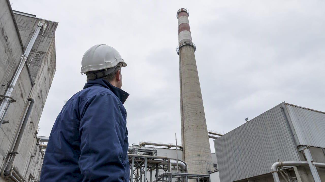
An industrial chimney needs a standards-compliant external lightning protection system sized through a documented risk analysis, with the protection level determined by that analysis, a capture device, at least two down-conductors, earthing, equipotential bonding and surge protective devices. The first step is commissioning an ARF (Analyse du Risque Foudre) and technical study to fix the protection level, referencing IEC 62305, before any hardware gets specified.
TL;DR:
- An ARF weighs chimney height, process hazards, and failure consequences; the protection level sets capture geometry, down conductor spacing, earthing targets, and surge device ratings.
- Give each down conductor its own disposition A electrode, connect all electrodes to the site earth loop, and install accessible test joints for resistance checks.
- Place Type 1 SPDs at the main service entry and coordinated Type 2 units near sensitive equipment; bond metal services to the LPS earth reference.
- PDA acceptance depends on the governing standard; specify its projection height, remote testability, and inspection access, while passive terminals require a documented protection zone.
- Record commissioning earth resistance at every test point, compare later readings against that baseline, and reinspect after strikes or chimney structural work.
Table of Contents
- Components of an External LPS for Chimneys
- Risk Analysis and Protection Levels Drive the Design
- Choosing Capture Devices: Air Terminals vs PDAs
- Down-Conductors, Test Points and Earthing to Manage Voltage Gradients
- Internal Protection Against LEMP: SPDs, Bonding and Cabling
- Separation Distance and Zone-of-Protection Checks
- Materials, Corrosion Protection and Fixation Near Exhausts
- Inspection, Testing and Maintenance Intervals
- Design Coordination: Bring in Lightning Protection Engineering Early
- On-Site Acceptance Checklist for Handover
- Why Standards-First Design Matters
- Indelec Services for Chimney Lightning Protection
- FAQ
- Sources
Components of an External LPS for Chimneys
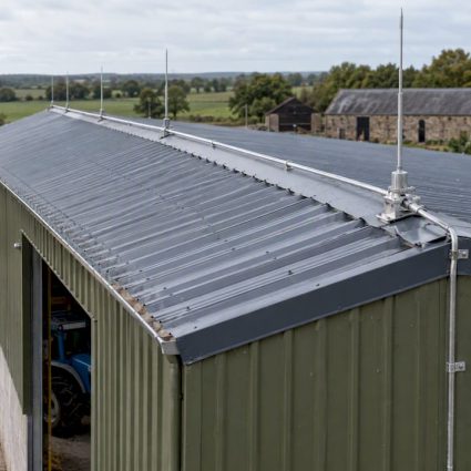
A compliant system for a chimney has interlocking parts. The capture device, whether a simple air terminal or a mast, intercepts the strike. Down-conductors carry that energy to ground, and earthing dissipates it safely into the soil. None of this works in isolation: every part has to bond back to the same reference potential as the rest of the facility.
- Strike termination devices sit above the chimney crown or on a dedicated mast, positioned so the structure falls inside the protected volume.
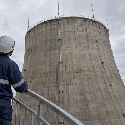
- Some chimney designs use multiple down-conductors routed on opposite sides to split the current path.
- Earthing follows disposition A, with each down-conductor terminating in its own electrode, interconnected across the site to avoid dangerous potential differences.
- Internal bonding and surge protective devices close the loop, protecting electrical systems from what the external LPS alone cannot stop.
Skipping the interconnection step is a common and costly mistake: an isolated electrode that is not tied into the site earth loop can leave equipment exposed even when the capture device and down-conductors are correctly sized.
Risk Analysis and Protection Levels Drive the Design
The ARF is where the real engineering decisions get made. It weighs the chimney’s height, its function within the plant, the probability of a strike reaching it, and the consequences of a failure, whether that is fire, process shutdown or harm to personnel nearby.
- Taller structures and those tied to flammable processes generally require a stricter protection level and a denser mesh of protection.
- Protection level I calls for tighter rolling-sphere radii and closer-spaced down-conductors than level IV, which tolerates a coarser design.
- The level chosen also sets the surge protective device ratings and the earth resistance targets the installation has to achieve.
An example technical study for a biomass cogeneration chimney illustrates this well: the ARF determined a Level IV classification for a 35-meter chimney, driving the choice of a PDA mounted 2 meters above the structure, two diametrically opposed down-conductors and specific earthing details. Document the ARF alongside the technical study and keep both on file with the references to the applicable IEC 62305 clauses.
Choosing Capture Devices: Air Terminals vs PDAs
A passive air terminal, often a simple rod or mast, protects a volume defined by the rolling-sphere method or an equivalent zone-of-protection reference, so its position on the chimney has to be checked against that geometry, not just bolted to the highest point.
A PDA, or early streamer emission device, is sized differently: specify the projection height above the chimney, confirm remote testability so a technician can verify function without climbing, and leave physical access for periodic inspection. Their normative status varies between frameworks, so confirm acceptance under the standard governing the project before specifying one.
- Device type (passive air terminal or PDA) and its height above the chimney crown.
- Mounting detail, including mast material, base fixing and wind load rating.
- Test point location and remote testability requirements.
- Reference standard and protection level the device is sized against.
Pro Tip:Specify the capture device’s protected volume on the drawing itself, not just in a text note, so installers and inspectors can check positioning visually against the rolling-sphere radius.
Down-Conductors, Test Points and Earthing to Manage Voltage Gradients
A metal chimney flue can sometimes serve as a natural down-conductor, but only when continuity and cross-section meet the standard’s requirements end to end; most masonry or lined chimneys need dedicated external conductors instead.
- Route down-conductors on diametrically opposed faces of the chimney, keeping bends gentle and avoiding sharp angles that increase impedance.
- Size conductors per the applicable standard, with bare copper flat or round sections sized to the protection level, as used in the biomass cogeneration example, where 30×2 mm bare copper flat conductor was specified.
- Terminate each down-conductor in a disposition A earth electrode, then interconnect the electrodes to the site earth loop with a bare copper conductor.
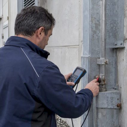
- Install accessible test joints at the bases of the down-conductors so earth resistance can be measured independently.
- Consider fitting strike counters so recorded events can be correlated against inspection findings.
IEC 62305-3:2024 sets the current rules for positioning air terminations, earthing and down-conductors on structures of any height, and it is the reference to cite in the technical study.
Internal Protection Against LEMP: SPDs, Bonding and Cabling
The external LPS stops a direct strike from destroying the chimney structure. It does nothing to protect motors, sensors, or control panels from the surge that travels through cabling. That is the job of coordinated surge protective devices and bonding.
- Install Type 1 SPDs at the main service entry, where the facility connects to the utility supply or the on-site generator.
- Add Type 2 SPDs at distribution boards and near sensitive process equipment, coordinated in let-through voltage with the Type 1 device upstream.
- Bond all metal services, cable trays and conduits to the same earthing reference used by the external LPS.
- Route sensitive signal cabling away from down-conductors and power cabling to limit magnetic coupling.
IEC 62305-4 covers this coordination directly, warning that lightning electromagnetic impulse can permanently damage electronic systems even without a direct strike, and it sets out the design and testing requirements for internal protection measures.
Separation Distance and Zone-of-Protection Checks
Any metal object near the chimney, ladders, platform rails, flue penetrations, instrumentation conduit, needs a separation distance check against the down-conductors and capture device. The question is simple: close enough to risk a side flash, or far enough to stay outside the danger zone.
- Calculate separation distance using either the simplified method for straightforward geometries or the general method from the standard’s annexes for complex layouts.
- When calculated clearance cannot be achieved, bond the nearby metal object directly to the LPS instead of leaving it isolated.
- Keep the separation distance calculation in the project file alongside the ARF and technical study, since inspectors and insurers will ask for it.
Materials, Corrosion Protection and Fixation Near Exhausts
Flue gases are corrosive, and that changes what you can specify close to the stack. Tin or lead coating is required on copper components within 600 mm of a chimney or vent exhaust, with stainless steel or other resistant alloys as compatible alternatives.
- Specify corrosion-resistant fixings and mast materials rated for the flue gas environment.
- Use approved bimetallic connectors wherever dissimilar metals meet, to prevent galvanic corrosion at the joint.
- Avoid aluminum grounding materials in direct soil or earth contact where the governing standard restricts them.
Inspection, Testing and Maintenance Intervals
A lightning protection system only works if it is maintained the way it was designed. Periodic verification catches loosened fixings, corroded joints and drifting earth resistance before they become a failure point during an actual strike.
- Inspect mechanically on the interval set by the protection level: visual checks of capture devices, conductor fixings and test joints.
- Measure earth resistance at each test point and compare it against the baseline recorded at commissioning.
- Read strike counters at each visit and log any recorded events against the maintenance file.
- Reinspect after any recorded strike or after structural work on the chimney, regardless of the scheduled interval.
Pro Tip:Ask for the commissioning earth resistance readings in writing before signing off on a new installation, since that baseline is what every later measurement gets compared against.
Demand test reports, measured earth resistances, a maintenance log and counter readouts at every handover, not just at the first one. Practical LPI guidance sets out the inspection detail that a maintenance contract should mirror.

Design Coordination: Bring in Lightning Protection Engineering Early
Retrofitting a lightning protection system onto a finished chimney almost always costs more and integrates less cleanly than designing it in from the start. Early consultation between the lightning protection engineer, chimney designer and facility architect keeps attachment points, conductor routing and structural supports coordinated before concrete or steel is finalized.
- Fix attachment points, conductor concealment routes and access platforms for inspection at the design stage, not after construction.
- Require the ARF, technical study drawings, a materials list, test point locations and a maintenance schedule as tender deliverables.
- Balance visual integration with safety: concealed conductor routing is fine as long as test joints stay accessible.
On-Site Acceptance Checklist for Handover
Before signing off, compare the finished installation against the specification point by point.
- Confirm the as-built protection level matches the ARF conclusion.
- Verify capture device height, positioning and protected volume against the drawing.
- Check down-conductor routing, test joint accessibility and measured earth resistance at each electrode.
- Confirm strike counter installation and readability.
- Verify SPD placement and review the equipotential bonding documentation.
- Confirm the maintenance schedule and inspection access have been handed over.
| Checklist item | What to verify |
|---|---|
| Protection level | Matches ARF conclusion |
| Capture device | Height and position against drawing |
| Down-conductors | Routing and test joint access |
| Earthing | Measured resistance at each electrode |
| Strike counter | Installed and readable |
| SPDs and bonding | Placement and documentation on file |
Why Standards-First Design Matters
Lightning protection that starts with a documented risk analysis outlives protection bolted on as an afterthought. We have seen that the projects with the fewest callbacks are the ones where the ARF, the technical study and the maintenance contract were locked in before the first conductor went up. Require the paperwork, not just the hardware.
— INDELEC
Indelec Services for Chimney Lightning Protection
We handle the scope for industrial chimneys: the ARF and technical study, capture devices from our paratonnerres range, down-conductors, earthing, surge protective devices and strike counters, through to installation and ongoing maintenance.

If you need temporary grounding equipment for a commissioning test, professional earthing rental partners can cover short-term needs while permanent electrodes are finalized. For your chimney, the next step is a site survey: request an ARF, ask for the resulting ET and maintenance plan, and get a firm protection contre la foudre proposal in hand before construction or retrofit work starts.
FAQ
Can lightning enter a building through its structure?
Yes, lightning current can travel through a structure via metal services, plumbing or structural steel if the building lacks bonding and a properly earthed lightning protection system. Coordinated external protection and internal bonding are what keep that current from reaching occupied spaces or sensitive equipment.
Is installing a lightning rod mandatory for every building?
Requirements depend on the structure’s risk profile, as determined by a risk analysis such as the ARF, and on the regulations covering the specific facility type and location. The facility type and location also affect the requirements. An ARF can help determine what protection is appropriate for a given site.
How long do surge protective devices typically last in service?
Service life depends on the device’s rating, how often it absorbs surges and the environment it operates in, so there is no single fixed figure. Periodic testing during scheduled maintenance is how you confirm a device is still within its working parameters rather than relying on age alone.
What do lightning protection levels mean in practice?
Lightning protection levels set design parameters for a system, with the selected level determined by the site’s risk analysis. The level determines the rolling-sphere radius used for capture device positioning, the spacing of down-conductors and the earthing targets, and it comes directly from the site’s risk analysis.
Sources
- SIST EN IEC 62305-3:2024 – Lightning Protection for Structures and
- INTERNATIONAL
- ETUDE TECHNIQUE FOUDRE COGENERATION PAPETERIES PALM DBI