Lightning Rod Down Conductor Connections: A Site Guide
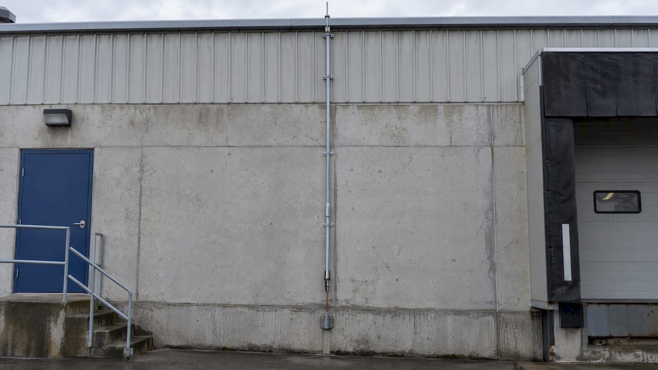
The connection between a lightning rod and its down conductors (in French, the raccordement de la descente du paratonnerre) is where most installations either work or quietly fail. The conductor must start on the body of the air terminal through a proper clamp or fitting, follow a short and direct path down the structure, pass through a test joint, and end in an earth termination that you can measure. This guide walks through each of those points for facility owners, contractors and maintenance teams working on French sites.
TL;DR
- The down conductor connects to the lightning rod through a dedicated fitting on the air terminal or mast, never through improvised clamps or twisted cable.
- Keep the route short, direct and free of sharp bends, and fix it at regular intervals along the façade.
- Every down conductor needs a test joint near the base so the earth connection can be isolated and measured during inspections.
- The rod, the down conductors and the earthing form one chain: a perfect connection at the top is worthless with a high-resistance earth.
- Before touching an older rod, confirm it is not a radioactive model. If it is, or if you are unsure, stop and call an authorized company.
Table of Contents
- What the connection has to do
- The five connection points, from tip to ground
- Why the earth decides everything
- Common mistakes we see on connections
- Surge protection: the connection rule everyone gets asked about
- Before you touch an older rod: check for radioactivity
- Inspection: what the auditor will look at
- Our perspective
- Getting the connections designed and checked
- FAQ
- Sources
What the connection has to do
When lightning hits the air terminal, the current must travel from the tip to the ground without finding another path. The down conductor is that path. Every joint on it adds resistance and inductance, and every sharp bend invites a side flash to nearby metalwork or cabling.
For a French site, the reference documents are the NF C 17-102 standard for systems using an early streamer emission (ESE) air terminal, and the NF C 17-100 / NF EN 62305 family for structures more broadly. You can check the scope and current edition of the ESE standard on the AFNOR page for NF C 17-102, and we keep a summary on our lightning standards page.
The standard tells you what to achieve. The specifics of your site, meaning building height, roof geometry, soil and what sits inside, come from the lightning risk analysis and the technical study. Those two documents set how many down conductors you need and where they run. The connection details below apply once that design exists.
The five connection points, from tip to ground
A down conductor run has five points where workmanship matters. We go through them in the order a current would travel.

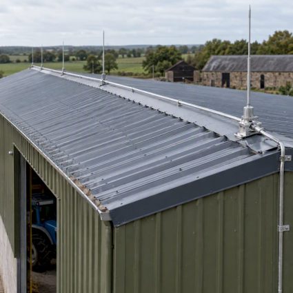
1. The air terminal or mast head
The conductor starts on the body of the lightning rod. Manufacturers supply a stainless steel connector or clamp for this purpose, sized for the conductor type (flat strip or round). Use the fitting that comes with the rod: it is part of the tested assembly, and mixing in generic clamps can introduce galvanic corrosion or a loose contact that you will only discover during an inspection.
Practical points at this stage:
- Tighten to the torque the manufacturer specifies, then recheck after the first thermal cycles on a new installation.
- Keep the contact surfaces clean. Remove any oxide or paint under the clamp before closing it.
- When the rod sits on a mast, the conductor is secured to the mast with collars rather than left hanging. Our mast and mast-fixing ranges are designed so the conductor start, the mast and the base fixing work as one assembly.
2. The conductor itself
Common materials are tinned copper strip, bare copper, galvanized steel, stainless steel or aluminum, chosen according to the environment and the other metals present. The rule that matters on site is compatibility: do not put copper in direct contact with aluminum or galvanized steel outdoors without a suitable bimetallic fitting, because moisture turns that junction into a corrosion cell.
You can browse our down conductor range to match conductor type with the fittings used at each end.
3. Joints and splices along the run
The best number of joints on a long run is as close to zero as the building allows. When one is unavoidable, use a fitting designed for lightning current, not an electrical terminal block. Crimped or bolted lightning connectors are rated for the conductor cross-section they join, and welded or brazed joints are an option on some conductor types.
A joint is acceptable when it is mechanically firm, protected against corrosion, and measures low resistance. If it is outdoors and exposed to weather, protect it accordingly.
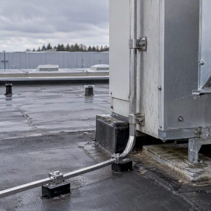
4. Fixings and routing
The route is part of the connection. Aim for a path that is:
- Direct: the shortest practical path from the rod to the earth, running vertically wherever possible.
- Free of sharp bends: avoid upward loops and tight corners. A conductor that climbs back up before descending gives lightning a reason to jump.
- Away from internal services: keep it clear of power and data cabling, gas lines and similar utilities, or interconnect and separate them as the design requires.
- Properly supported: fixings spaced regularly so wind, thermal movement and snow do not pull the conductor off the wall.
For most buildings, the technical study specifies at least two down conductors where height or geometry requires it, preferably on different façades. Where there are several rods on one structure, they are interconnected as the design dictates. These numbers depend on the standard and the building, so take them from your study, not from a rule of thumb.
Our range of conductor connections and fixings covers clamps, supports and routing accessories for flat and round conductors across common wall and roof types.
5. The test joint and the earth termination
Near the base of each down conductor, a test joint (inspection clamp) allows you to open the circuit and measure the earth electrode on its own. It should be marked, accessible and protected from mechanical damage. The lower section of the conductor, the part exposed to impacts and passers-by, is often protected by a sleeve or guard.

Below the test joint, the conductor connects to the earth termination. The connection to the earth electrode is the most commonly neglected, because it is buried or hidden. Use a fitting rated for in-ground use, and keep records of where it is, with photos before backfilling.
Why the earth decides everything
A correctly clamped rod and well-routed conductors cannot compensate for a poor earth. High resistance in the ground connection stops the current from dispersing and pushes it toward other paths, including the building’s electrical network. Schneider Electric’s regulatory guidance stresses that the earth quality governs the effectiveness of both rods and surge protectors, and that the building’s earthing systems should be interconnected to avoid dangerous potential differences during storms.
In practice:
- Measure the earth resistance at commissioning, through the test joint with the conductor open.
- Bond the lightning earth to the building’s main earthing system, as the design specifies.
- In rocky or high-resistivity soil, consider deeper electrodes. We run deep earth grounding drilling for exactly these cases.
- Record every measurement so the next inspector can compare it with the last.
Our earthing range and our guide to maintaining grounding systems cover the hardware and upkeep side.
Common mistakes we see on connections
| Mistake | Why it matters | What to do instead |
|---|---|---|
| Generic clamp on the rod body | Loose contact, corrosion, voids the assembly logic | Use the fitting supplied for that air terminal |
| Mixed metals without a bimetallic fitting | Galvanic corrosion at the joint | Match materials or use a suitable transition fitting |
| Tight loops or upward runs | Side flashes to nearby metalwork | Route directly downward with generous radii |
| No test joint, or one buried in render | Earth cannot be measured, inspection fails | Install an accessible, labeled joint |
| Down conductor passed through the roof next to cabling | Induced voltages on signal and power lines | Keep separation or bond as designed |
| Untracked modifications | New equipment sits outside the studied protection | Update the risk analysis after changes |
Surge protection: the connection rule everyone gets asked about
Readers searching for this topic often confuse down conductor connections with surge protector wiring. They are different chains, but they fail in similar ways.
For surge protectors on the electrical network, the NF C 15-100 guidance sets the cumulative length of the conductors from the network to the surge protector and then to the earth terminal block at no more than 50 cm. Beyond that, the extra cable impedance leaves a high residual voltage at the equipment, and the device protects far less than its rating suggests. The same source states that since August 2024 the standard makes surge protection mandatory in non-residential buildings, including industrial, public service and health facilities.
The lightning rod handles direct strikes on the structure. Surge protectors handle overvoltages entering through the cabling. You need both. See our surge protection range and the installation guide for facilities.
Before you touch an older rod: check for radioactivity
If your building dates from before the late 1980s, the rod on the roof may be a radioactive model. The INRS publication on radioactive lightning rods covers rods made between 1932 and 1986, and its guidance is plain: if a rod is radioactive, or you cannot tell, do not touch it, keep a distance of about 3 meters, and use an authorized company for any removal or work nearby.
This affects connection work directly. Re-terminating a down conductor on an unidentified legacy rod is exactly the type of intervention that must wait until its status is known. For classified installations (ICPE), the 2010 order requires radioactive rods to be removed under the conditions it sets.
Inspection: what the auditor will look at
For ICPE sites covered by the 2011 amendment, the order requires an initial inspection within six months of installation, a visual inspection every year, and a complete inspection every two years by a competent, independent body, with each inspection recorded. The earlier 2008 order provides that, following the lightning risk analysis, a technical study by a competent body defines the protection measures and where they are placed.
On the connections, an inspector typically checks:
- The condition and tightness of the fittings at the rod and along the run.
- Continuity of the conductor between rod and test joint.
- Earth resistance measured at the test joint.
- Whether the installed system matches the technical study, and whether the site has changed since.
Our articles on closing the six-month, annual and two-year gaps and on insurer expectations for ICPE sites show how sites fall behind and how to catch up.
Our perspective
We have been in lightning protection since 1955, with more than 280,000 installations behind us, and the same pattern keeps appearing: failures rarely come from the rod itself. They come from the interfaces. A clamp that was not the right one, a joint buried before anyone measured it, a conductor rerouted around a new rooftop unit, an earth that was never checked after the first year.
That is why we design the rod, mast, fixings, down conductors and earthing as one system, and why our R&D work treats the connections as seriously as the air terminal. It is also why we push clients toward a documented risk analysis and technical study before any hardware is chosen. The number and routing of down conductors is a design output, not a catalog decision.
Our advice to maintenance teams: photograph every joint before it is covered, label every test joint, and keep a single file with the study, the as-built drawings and each measurement. The next inspection takes a fraction of the time.
— INDELEC
Getting the connections designed and checked
If you are specifying a new system or inheriting an old one, we can take it from risk analysis and technical study through installation, inspection and maintenance. Start with our lightning protection services, or browse the lightning rod range if you already have a design and need matching components.
FAQ
How many down conductors does a lightning rod need?
It depends on the type of air terminal, the height of the building and the layout of the roof. A common design uses at least two conductors on different façades once the structure or the route exceeds the limits in the standard. Your technical study sets the number for your site, so do not rely on a general rule.
What is the 50 cm rule for surge protectors?
It limits the cumulative length of the conductors linking the network to the surge protector and the surge protector to the earth terminal block. Per the NF C 15-100 guidance, that total should not exceed 50 cm. Longer leads raise the residual voltage at your equipment.
Can I replace a lightning rod and reuse the old down conductor?
Only after checking the old conductor’s condition, fittings and earth, and confirming the replacement is compatible with its cross-section and material. If the old rod might be radioactive, do not touch it and contact an authorized company first. A new rod is a good moment to rerun the risk analysis.
Do I need a test joint on every down conductor?
In standard practice, yes: each down conductor needs a way to isolate its earth and measure it. Without one, the inspector cannot verify the earth resistance independently, and the installation is likely to be flagged. Check the exact requirement against the edition of the standard your design follows.
Sources
- Schneider Electric France: surge protector standard and regulation
- INRS: radioactive lightning rods (ED 4447)
- Légifrance: order of 19 July 2011, article 2
- Légifrance: order of 15 January 2008, article 3
- Légifrance: order of 4 October 2010
- AFNOR: NF C 17-102 standard