How to Maintain Grounding Systems: A Practical Guide
Maintaining grounding systems comes down to three non-negotiable tasks: visual inspection, ground resistance testing, and documented corrective action. Done right, these steps keep fault current on a controlled path, protect personnel from shock, and keep you compliant with IEEE Std 142, the NEC, and OSHA standards. Skip any one of them and you have a system that looks fine until it fails. For more on the importance of grounding continuity and inspection, see oude elektrische bedrading risico’s.
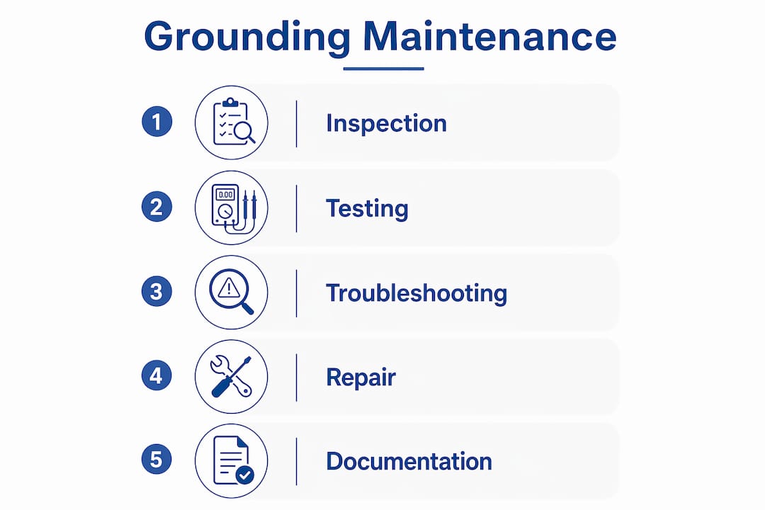
Here is what a complete maintenance program covers:
- Visual inspection: Check for corrosion, loose or broken connections, and physical damage at every electrode, conductor, and earth bar terminal.
- Resistance testing: Confirm earth resistance is below 2Ω with the grid connected and below 5Ω when disconnected.
- Connection maintenance: Tighten mechanical fittings, clean oxidized surfaces, and replace degraded conductors.
- Documentation: Record every test value, observation, and corrective action with date and technician signature.
- Scheduling: Inspect at least annually; increase frequency at sites with high corrosion exposure or frequent lightning activity.
Table of Contents
- 1. How to inspect your grounding system visually
- 2. How to test ground resistance accurately
- 3. Interpreting test results and spotting poor grounding
- 4. What a real maintenance scenario looks like
- 5. Best practices from Indelec’s decades of grounding expertise
- Indelec brings specialized grounding expertise to your facility
- Key Takeaways
1. How to inspect your grounding system visually
Visual inspection is the first line of defense, and it catches most problems before they show up on a meter. The goal is to trace the entire grounding path from the electrode in the earth pit to the earth bar, then from the earth bar through every bonding conductor to connected equipment.
Step-by-step inspection checklist:
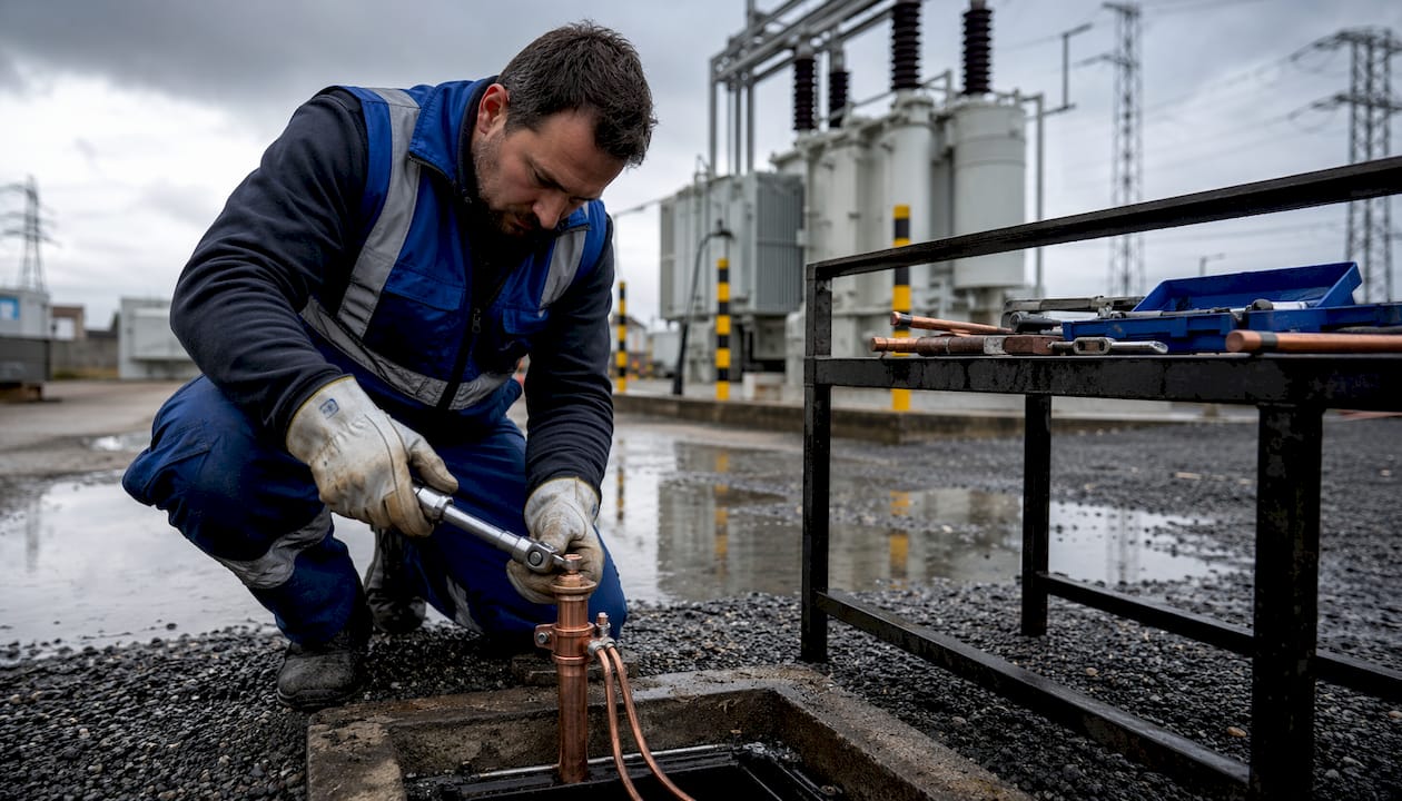
- Open the earth pit cover and look for standing water, soil intrusion, or visible corrosion on the electrode and clamp.
- Check that the electrode surface is free of nonconductive coatings such as paint, enamel, or heavy oxide scale, since coated electrodes cannot make reliable soil contact.
- Inspect all mechanical connections at the earth bar: look for green or white oxidation, cracked lugs, and missing hardware.
- Trace bonding conductors along their full run, checking for cuts, abrasion damage, or unsupported spans that could introduce mechanical stress.
- Examine conduit entry points and cable glands for moisture ingress that accelerates conductor corrosion.
- Photograph every finding and note its location on a site sketch for the maintenance record.
Preventive tasks run in parallel with inspection. Tighten every mechanical connection with a calibrated torque wrench, clean oxidized surfaces with a wire brush and apply an anti-oxidant compound, and replace any conductor showing more than surface corrosion. Electrode and conductor connections commonly fail from corrosion and loose fittings, so annual tightening checks are not optional.
PPE requirements: Before opening any earth pit or touching bonding conductors, wear insulated gloves rated for the site voltage, safety glasses, and steel-toed boots. Use lock-out/tag-out (LOTO) protocols when working near live panels.
Pro Tip:Look at the earth bar bolts last. Technicians routinely inspect the electrode and miss that the bar itself has backed off its mounting by a half turn, adding several ohms of contact resistance at the most critical junction in the system.
Schedule inspections regularly for standard commercial facilities. Sites with corrosive environments or frequent lightning activity warrant more frequent inspections. Soil conditions matter too: sandy or rocky soils dry out faster and can push resistance values above acceptable limits between annual checks.
2. How to test ground resistance accurately
Ground resistance testing gives you the number that tells you whether the system can actually do its job. The Fall of Potential method is the recognized standard technique in the US, and it is what OSHA references for single-electrode compliance.
Equipment you need:
- A calibrated earth resistance tester (three-terminal or four-terminal clamp-on for large grids)
- Two auxiliary electrodes: a current stake © and a potential stake (P)
- Connecting leads long enough to achieve correct spacing
- A site diagram showing electrode locations
Fall of Potential procedure:
- Obtain a permit to work and confirm LOTO is in place on all connected panels.
- Disconnect the ground electrode from the grid. Leaving it connected produces a falsely low reading because parallel paths through the grid mask the true electrode resistance. Disconnecting the electrode before testing is the single most common procedure error in the field.
- Drive the current stake © at least 30–40 meters from the test electrode in a straight line away from any buried metalwork.
- Place the potential stake (P) at 62% of the C-to-electrode distance along the same line. This is the standard 62% rule derived from the Fall of Potential theory.
- Connect leads from the tester to the test electrode (E), potential stake (P), and current stake ©.
- Run the test and record the resistance value.
- Move the P stake 10% closer and 10% farther, retest both positions. If all three readings agree within roughly 5%, the middle value is valid. Wide variation means the stakes are too close to buried metalwork or each other.
- Reconnect the grid and retest to confirm the connected value.
| Condition | Target resistance | Action if exceeded |
|---|---|---|
| Grid connected | Below 2Ω | Investigate bonding path; add electrodes |
| Electrode disconnected | Below 5Ω | Improve soil contact or install additional rod |
| Single electrode (OSHA) | — | Add a second electrode at least 6 ft away |
Calibrate your tester annually and verify it against a known reference before each test campaign. A tester that drifts by even 0.5Ω can push a borderline result into a false pass.
3. Interpreting test results and spotting poor grounding
A resistance reading above threshold is the clearest signal, but grounding problems often announce themselves through equipment behavior before anyone picks up a tester.
Common signs of a compromised grounding system:
- Erratic operation of sensitive electronics or PLCs with no apparent cause
- Electrical noise or interference on signal cables running near power conductors
- Flickering lights or nuisance tripping of breakers under normal load
- Mild shocks when touching metal enclosures or equipment frames
- Ground fault indicators that trip and reset without a clear fault source
When resistance exceeds the thresholds in the table above, the first troubleshooting step is to check mechanical connections at the earth bar and electrode clamp. Loose fittings and corroded contact surfaces account for a large share of out-of-spec readings. If tightening and cleaning bring the value back within range, document the finding and increase inspection frequency for that pit.
If resistance remains high after connection work, the problem is likely in the soil contact. Dry or sandy soil, frost, or a cracked electrode all reduce the effective contact area. Adding a second electrode spaced at least 6 feet from the first is the code-compliant fix under OSHA 1926.404. Continuous monitoring with a permanent resistance logger helps catch intermittent faults that only appear under specific soil moisture conditions.
4. What a real maintenance scenario looks like
A manufacturing facility in the Midwest runs annual earth pit maintenance every March, before the summer storm season. The maintenance team follows a written SOP aligned with the MSHA inspection guidelines and documents every step with photos and a signed checklist.
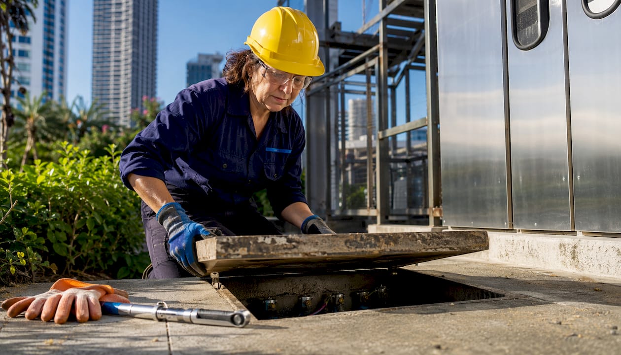
During one inspection cycle, the technician opened the earth pit at the main switchgear building and found green oxidation on the copper conductor clamp and a resistance reading of 4.8Ω with the grid disconnected. That value was within the 5Ω limit but trending upward from 3.2Ω the previous year.
The corrective action took under an hour. The documentation captured the before and after values, the technician’s name, the tools used, and the next scheduled check date. That record satisfies both internal audit requirements and external compliance reviews under IEEE Std 142 and OSHA. The electrode layout sketch, showing the test electrode position and the C and P stake placements, was attached to the checklist as a reference for the next technician.
5. Best practices from Indelec’s decades of grounding expertise
Grounding maintenance done well goes beyond checking the earth pit once a year. Indelec’s field experience across industrial, infrastructure, and energy sector projects points to several practices that separate reliable systems from ones that pass inspection but fail in service.
Verify bonding integrity, not just electrode resistance. A low pit resistance reading can coexist with a broken bonding conductor between the electrode and the earth bar. That break leaves the entire downstream system unprotected even though the electrode itself is fine. Check mechanical tightness and corrosion-free contact at every junction in the bonding chain, not just at the pit.
Avoid salt-water treatments as a long-term fix. Pouring salt water into an earth pit to lower resistance is a short-term measure that accelerates electrode corrosion and creates a bigger problem within a few seasons. Mechanical improvements, such as deeper electrodes, multiple rods, or conductive backfill materials, deliver durable results without degrading the electrode.
Use high DC current continuity testing in substations. Standard low-current testers miss internal grid deterioration in large substation grounding grids. High DC current testing up to 300A provides non-destructive detection of open circuits and deteriorated connections that a standard tester would pass. Indelec’s grounding technology expertise covers this method in detail for energy sector applications.
Stay current with grounding compliance standards. IEEE Std 142, NEC Article 250, and OSHA 1926.404 set the floor. Facilities with lightning exposure also need to align with NFPA 780 and verify that their grounding system integrates correctly with the lightning protection network. Indelec’s R&D-backed approach to system design and maintenance reflects these layered requirements.
Pro Tip:When you update a facility’s plumbing from metal to plastic pipe, the old water pipe ground electrode is no longer valid. Modern electrical codes require a dedicated grounding electrode system in that case. Audit your electrode inventory whenever building infrastructure changes.
Indelec brings specialized grounding expertise to your facility
Grounding system maintenance requires more than a checklist. It requires the right testing methodology, accurate interpretation of results, and corrective action that holds up under the next inspection cycle.

Indelec has been designing, installing, and maintaining grounding and lightning protection systems since 1955, with projects spanning industrial plants, infrastructure facilities, and commercial buildings across the US and globally. Where a standard maintenance contractor checks resistance and moves on, Indelec’s technical teams assess bonding integrity across the full grounding path, apply advanced testing methods for complex grids, and deliver documentation that satisfies IEEE, OSHA, and NEC compliance requirements. For facilities that need deep earth grounding in difficult soil conditions, Indelec’s specialized drilling services reach the electrode depths that surface rods cannot. Contact Indelec to schedule a grounding system assessment for your facility.
Key Takeaways
Effective grounding system maintenance requires annual inspection, resistance testing against defined thresholds, and documented corrective action to stay compliant with IEEE, NEC, and OSHA requirements.
| Point | Details |
|---|---|
| Annual inspection minimum | Inspect at least once per year; increase to every six months in corrosive or lightning-prone environments. |
| Resistance thresholds | Target below 2Ω with the grid connected and below 5Ω with the electrode disconnected. |
| Disconnect before testing | Always disconnect the electrode from the grid before Fall of Potential testing to avoid falsely low readings. |
| Bonding integrity matters | A low pit resistance reading does not confirm system health; verify every mechanical connection in the bonding chain. |
| Indelec grounding services | Indelec provides full-path grounding assessments, advanced testing, and compliance documentation for industrial and commercial facilities. |