Fall of Potential Test: Method, Steps and Pitfalls
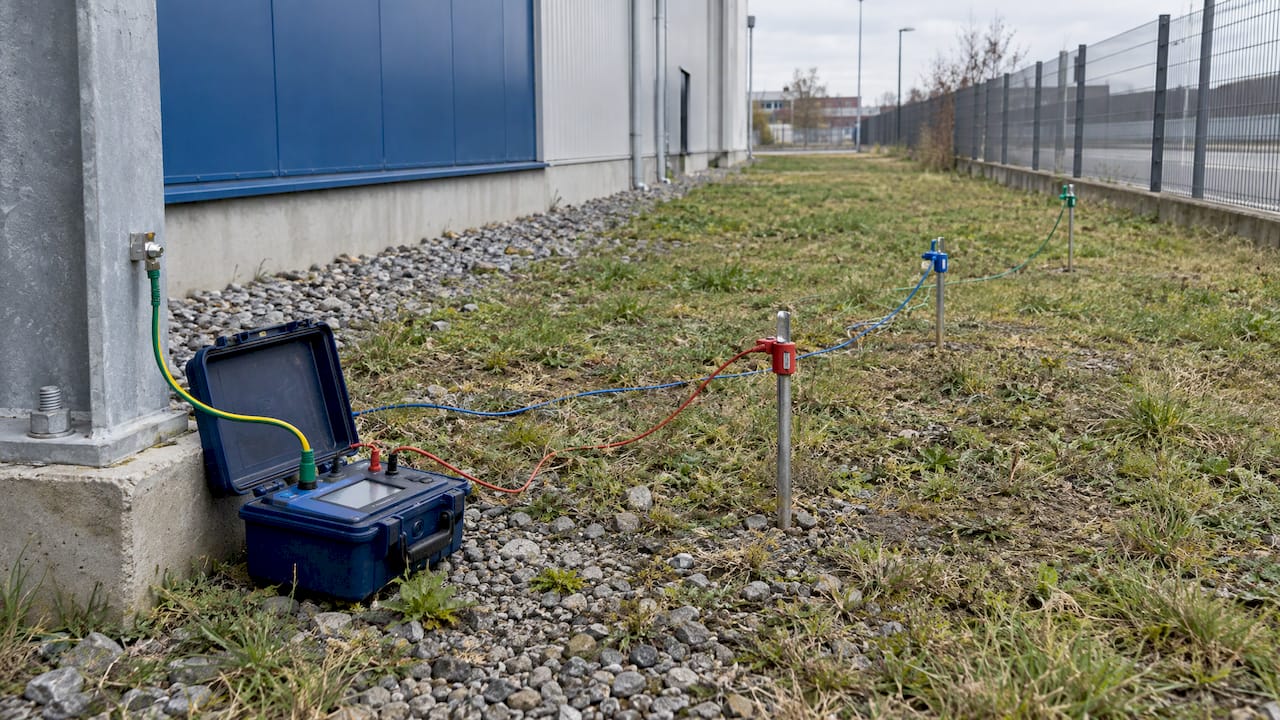
A fall of potential test measures the resistance of an earth electrode or earthing system by injecting current through the ground and reading the voltage drop with a separate probe. You drive a current probe far from the electrode, place a potential probe on the same line, and read resistance from Ohm’s law. The result is only reliable if the electrode is isolated, the probes are far enough away, and you prove the reading is stable by moving the potential probe. This guide covers each of those steps, the errors that ruin results, and where continuity testing fits in.
TL;DR
- The method injects current between the electrode under test (E) and an auxiliary current probe (H), then measures voltage between E and a potential probe (S). Resistance is voltage divided by current.
- Disconnect and isolate the earthing system first, and make sure it is de-energized before touching any link.
- Place S at about 62% of the E to H distance, then move it to either side and compare readings to check the result is valid.
- Probes placed too close are the most common cause of wrong results. Placing H farther than the minimum does no harm.
- Ground or bonding continuity testing checks a conductive path with a low-resistance meter. It does not replace an earth resistance measurement.
Table of Contents
- What the fall of potential method actually measures
- Before you test: isolation and safety
- How to perform a three-point fall of potential test
- Quick reference: layout rules compared
- Common errors that make results unreliable
- When fall of potential is not the right method
- Ground continuity and bonding continuity tests
- Reading the numbers
- Perspective
- Get your earth termination verified
- FAQ
- Sources
What the fall of potential method actually measures
The basic problem of any earth measurement is that you need a voltage reference somewhere. As the Swiss federal inspectorate explains in its technical report on earth resistance measurement, you must contact the voltage measurement once on the earth electrode and once in ideal, distant, neutral soil. The voltage drop method is the basic principle that solves this.
The setup uses three connections, which is why people also call it the 3-point or 3-pole test:
- E: the electrode or earthing system under test.
- H: an auxiliary current probe, driven far from E. Current flows through the soil between E and H.
- S: an auxiliary potential probe, placed on the line between E and H. The tester measures the voltage between E and S.
The tester divides the measured voltage by the injected current. The principle rests on Ohm’s law: the ratio of voltage drop to circulating current gives the resistance at the position of the potential probe.
The third probe is the reason the method works well. It avoids the error that would come from the resistance of the auxiliary current electrode, because the voltage is read between E and S rather than across the whole current loop.
Why the resistance area matters
Every electrode has a zone of soil around it where most of its resistance is concentrated. As Metrel’s application page explains, the probes must be far enough apart that these zones do not overlap. If S is too close to E, the result is too low. If S and H are too close together, the zone of H affects the result.
The whole layout, the 62% rule and the validity checks below are about keeping those zones separate.
Before you test: isolation and safety
The first check is not about probes. Before starting, verify that the earthing system under test is de-energized and isolated from other earthing systems. Besides safety, this ensures the readings reflect the system you intend to measure rather than a parallel path through other grounded installations.
In practice:
- Identify the electrode and its test link or disconnection bar. In French installations this is typically the barrette de coupure, which isolates the earth electrode from the rest of the installation.
- De-energize the installation before opening any link. An electrode disconnected from a live installation leaves people unprotected, so cut the power first.
- Confirm there are no buried metallic services, parallel earth paths or stray voltage that you cannot control. If you cannot control them, stop and rethink the method.
- Reconnect the link and restore protection once the measurement is done, and record that you did.
For lightning protection earth terminations on industrial sites, this isolation step usually means coordinating with the facility manager, since opening a test link changes the protection state of the building. Plan the intervention, and keep it short.
How to perform a three-point fall of potential test
The procedure below follows the commonly published instrument practice for small to medium electrodes.
Step 1: lay out the probes
Drive the current probe 30 to 50 meters from the electrode under test, and the potential probe halfway between them. Aligning all three in a straight line is essential, according to a manufacturer’s operating manual.
The distance depends on the size of the electrode. Two published rules of thumb:
- The distance D between E and H should be at least 5 times the largest dimension of the object being measured, with S placed at 62% of D from E.
- Place the current probe at least 8 to 10 times the depth of the earthing system. For a ring or grid, use its longest diagonal as the dimension in that calculation.
Placing H farther than the minimum has no negative effect on the measurement, while placing it too close can make the result invalid. When space allows, go farther.
Step 2: apply the 62% rule
The 62% rule places the potential probe at roughly 62% of the E to H distance, measured from E. The approximate earth resistance is obtained when X = 0.62 D. The figure comes from a mathematical derivation for the particular case of a hemispherical electrode, as one technical article on earth resistance measurement notes. That is why you verify it on site rather than trust it blindly.

A worked example: with H at 100 m from E, S goes at 62 m. A French field practice using the same method uses a 62 m stake for the potential probe and a 100 m stake for the current probe.
Step 3: take the reading
Connect the tester to E, S and H with the leads kept apart so they do not couple with one another. Inject the test current and read the resistance. Note the soil conditions, the date and recent weather, because moisture changes the value.
Step 4: prove the reading is valid
One reading proves nothing. Move the potential probe and compare.
- The Megger manual says to move S 3 m beyond its initial position, then 3 m the other way, and take a reading at each. If the three readings agree within the prescribed tolerance, their average can be used. If not, use another method such as the 61.8% rule or the slope method.
- IEC 60364-6 advises moving S by 6 m each side, with the reading not changing by more than 10%. If it does, move the probes farther from the electrode.
- A French guide on the 62% method uses a 1 m displacement of the potential stake on either side, which must not change the measurement. Otherwise, increase the spacing of the auxiliary stakes and start again.
- A French practical guide describes readings at 52%, 62% and 72%. With no stable plateau, change the axis or the distance. Stop if buried networks, stray voltage or the laying area are not under control.
The tolerances differ between sources, so use the one your instrument manual or the applicable standard specifies, and write down which one you used.
Quick reference: layout rules compared
| Parameter | Typical guidance | Source |
|---|---|---|
| H distance from E | 30 to 50 m for small electrodes | Instrument manual |
| H distance, large systems | At least 5 times the largest dimension | Metrel |
| H distance, by depth | 8 to 10 times the system depth | Application note |
| S position | About 62% of D from E | Technical article |
| Validity check | Move S and compare readings | IEC 60364-6 via Metrel |
Common errors that make results unreliable
Probes too close. This is the leading cause of bad data. Overlapping resistance areas make the reading too low or distort it. Respect the distances above, and go farther when you can.
Probes not in line, or not isolated. A bent layout changes the geometry the 62% rule assumes. A system that is still bonded to other earths gives a value for the whole network, not the electrode.
Stray ground currents. Galvanic direct currents or leakage currents can corrupt readings. The remedy is to inject alternating current at a frequency different from the supply network and its harmonics. Portable generators typically supply between 85 Hz and 135 Hz. The Swiss report adds that measurements use non-harmonic frequencies such as 91, 97, 111 and 128 Hz to avoid polarization effects, and that the open-circuit measurement voltage may exceed 50 V only if the no-load current is limited to 10 mA.
Too few points on large grids. A full profile of a large grid needs many readings. One comparison of methods notes that a true test uses at least nine measurement points, one every 10% of the distance between E and H. Fluke sells test instruments, so treat that as a reminder of the principle rather than a procedure for your site.
Treating a qualitative standard as a quantitative one. For extended earthing systems, French and international standards give a qualitative method but no clear quantitative approach. The authors of that 2019 paper complement the measurement campaign with software simulation to confirm how the fall of potential results should be interpreted. For a large industrial site, plan on engineering interpretation, not just a meter reading.

When fall of potential is not the right method
The method is the elementary approach for earth electrodes, but it suits only small, simple electrodes because of the available area. Alternatives exist for constrained sites.
- Triangle method. With two auxiliary stakes, it is used when the 62% method is not feasible, for example when alignment is impossible or an obstacle prevents moving H far enough. It is less accurate and should not be treated as a reference method. Even when values look close, influence zones may overlap, so repeat with greater distances.
- Phase to PE loop measurement.It allows measurement in urban settings without driving a stake, at the cost of measuring a loop, not the isolated electrode.
- Three-earth (Blavier) method. It uses two auxiliary earths about 25 m apart forming an equilateral triangle, with the unknown calculated as x = (R1 + R2 – R3) / 2, according to a hobbyist document. Use it as background, and apply the same rule: cut the power before disconnecting any earth.
Ground continuity and bonding continuity tests
These are different tests with a different question. Fall of potential asks how well the electrode dissipates current into the soil. Continuity asks whether an unbroken low-resistance conductor path exists.
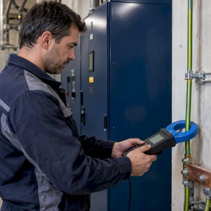
Protective conductor (PE) continuity verifies that an electrical path exists between the installation’s reference point and the accessible exposed parts. It is prepared with the installation de-energized. A suitable continuity tester applies a measuring current and reads a low resistance. In France, on a 230/400 V 50 Hz low-voltage installation, this is part of the regulatory checks, according to the same guide.
A practical procedure for ground or bonding continuity:
- De-energize the installation and confirm it.
- Pick a reference point, for example the main earthing terminal.
- Null or record the lead resistance of your tester.
- Measure from the reference point to each exposed conductive part, bonding conductor or equipotential link.
- Record each value and investigate any that are high compared with similar runs.
Do not substitute one test for the other. A good earth value does not compensate for poor PE continuity, and a poor value means you must look for the cause. Earth, PE, equipotential bonding, residual current devices and the panel work together.
Reading the numbers
Ohms alone do not tell you whether a site is compliant. The target depends on the type of installation and on the protection scheme. For example, for domestic installations in France, the earth resistance must not exceed 100 ohms, with lower-sensitivity RCDs required if soil quality prevents it. That is a domestic figure. Industrial sites, substations and lightning protection systems have their own requirements, set by the applicable standards and the site study.
Track the trend as much as the single value. A rising resistance over successive inspections points to corrosion, drying soil or damaged connections. Our guides on ground resistance: how to measure, read and fix it and earth resistance for electricians go deeper on interpretation, and how to maintain grounding systems covers inspection intervals and upkeep. If safety near a fault is your concern, read about step potential.
Perspective
We have been working on lightning protection since 1955, and in our experience the measurement is rarely the hard part. The hard part is deciding what the number means for a given site: the soil, the buried services, the way the earth termination is tied into the lightning protection system and the building’s earthing.
That is why we treat testing as part of a complete approach. A lightning risk analysis and technical study define what the earth termination must achieve. Installation builds it, and verification and maintenance confirm over time that it still does. A single reading in a dry month says little. A documented series, taken the same way each time, tells a facility manager far more.
When surface space or soil conditions limit what a driven electrode can reach, deep earth solutions are designed for exactly those sites, and our teams can advise on the right approach for yours.
INDELEC
Get your earth termination verified
If you manage an industrial, commercial or public site and need earthing and lightning protection verified, we can help. Our services cover lightning risk analysis and technical study, installation, and verification and maintenance, as well as deep earth electrodes for difficult ground. See our lightning protection services to describe your site and request support.

For hardware, browse our earthing products, or read about deep earth grounding drilling.
FAQ
What is the 3-point test for grounding?
It is the fall of potential test. You connect the electrode under test (E), a current probe (H) and a potential probe (S) placed on a straight line between them. The tester injects current between E and H, measures the voltage between E and S, and displays the resistance.
How far apart should the probes be?
For small electrodes, published instrument practice places the current probe 30 to 50 m away, with the potential probe halfway or at about 62% of that distance. For larger systems, use at least 5 times the largest dimension, or 8 to 10 times the depth. Farther is safer than closer.
How do I know my fall of potential result is valid?
Move the potential probe a few meters on each side of its position and read again. If the readings agree within the tolerance in your standard or instrument manual, the result holds. If they do not, increase the spacing of the probes and repeat.
Is a continuity test the same as an earth resistance test?
No. A continuity test checks that a low-resistance path exists between the reference point and exposed conductive parts. An earth resistance test measures how the electrode itself dissipates current into the soil. A compliant installation needs both.
Sources
- Mesure et documentation de la résistance de terre (ESTI)
- An Introduction to the Fall-of-Potential Method (EE Power)
- Earthing measurement with fall of potential method (Metrel)
- Fall-of-Potential Testing application note 3640 (AEMC)
- Megger DET2/2 operating manual
- Mesure de la résistance de la terre (Amperis)
- Méthode de mesure en ligne dite des 62%
- Vérifier une prise de terre (ElecFrance)
- Mesurer la continuité PE (ElecFrance)
- Réalisation et mesure des prises de terre
- Extended Earthing System Impedance Measurements (Springer, 2019)
- La mesure de terre (Chauvin Arnoux)
- Mesure de prise de terre domestique
- Mesure de terre, mise en service des installations domestiques