Cooling Tower Lightning Protection in France: Checks Every 2 Years
Protecting a cooling tower from lightning strikes requires a site-specific Analysis of Lightning Risk (ARF) built on NF EN IEC 62305-2, paired with a system of air terminals, downconductors, equipotential bonding, a low-impedance earth network and coordinated surge protection devices. ICPE status can add obligations on top of the standard, and every installation needs scheduled verifications on file. The immediate next step for most sites: confirm an annual visual check and a full verification every two years are already booked.
TL;DR:
- The ARF under NF EN IEC 62305-2 sets the protection level; certain ICPE classifications add mandatory measures, and major site changes require an updated analysis.
- Wide, open towers generally need distributed capture points rather than one central mast; corrosion resistant fixings and accessible bonds support inspection in spray and vibration.
- Coordinate Type 1, Type 2, and Type 3 surge protection from main switchgear to local panels, and bond each device to the site earth network.
- Tie the tower’s low impedance earth network to the facility’s main system; high soil resistivity often favors deep electrodes over a simple ring.
- Complete initial verification within six months, test continuity at every joint during biennial checks, and inspect within a month after a recorded strike, repairing damage promptly.
Table of Contents
- How lightning protection works on a cooling tower: components and their roles
- What standards and regulations require for cooling tower protection
- Commissioning the ARF and technical study (ET): inputs and outputs
- Designing and placing protection on a cooling tower structure
- Surge protection for the electrical systems around a cooling tower
- Grounding and earth network design for cooling tower sites
- Installation, verification and maintenance: the schedule that keeps protection valid
- Quick-spec checklist for design review and handover
- Why work with a qualified lightning protection specialist
- Balancing safety, uptime and lifecycle costs
- How we help design, install and maintain cooling tower protection
- FAQ
- Sources
How lightning protection works on a cooling tower: components and their roles
A cooling tower’s lightning protection system is only as strong as its weakest connection, so each component has a distinct job and none works in isolation.
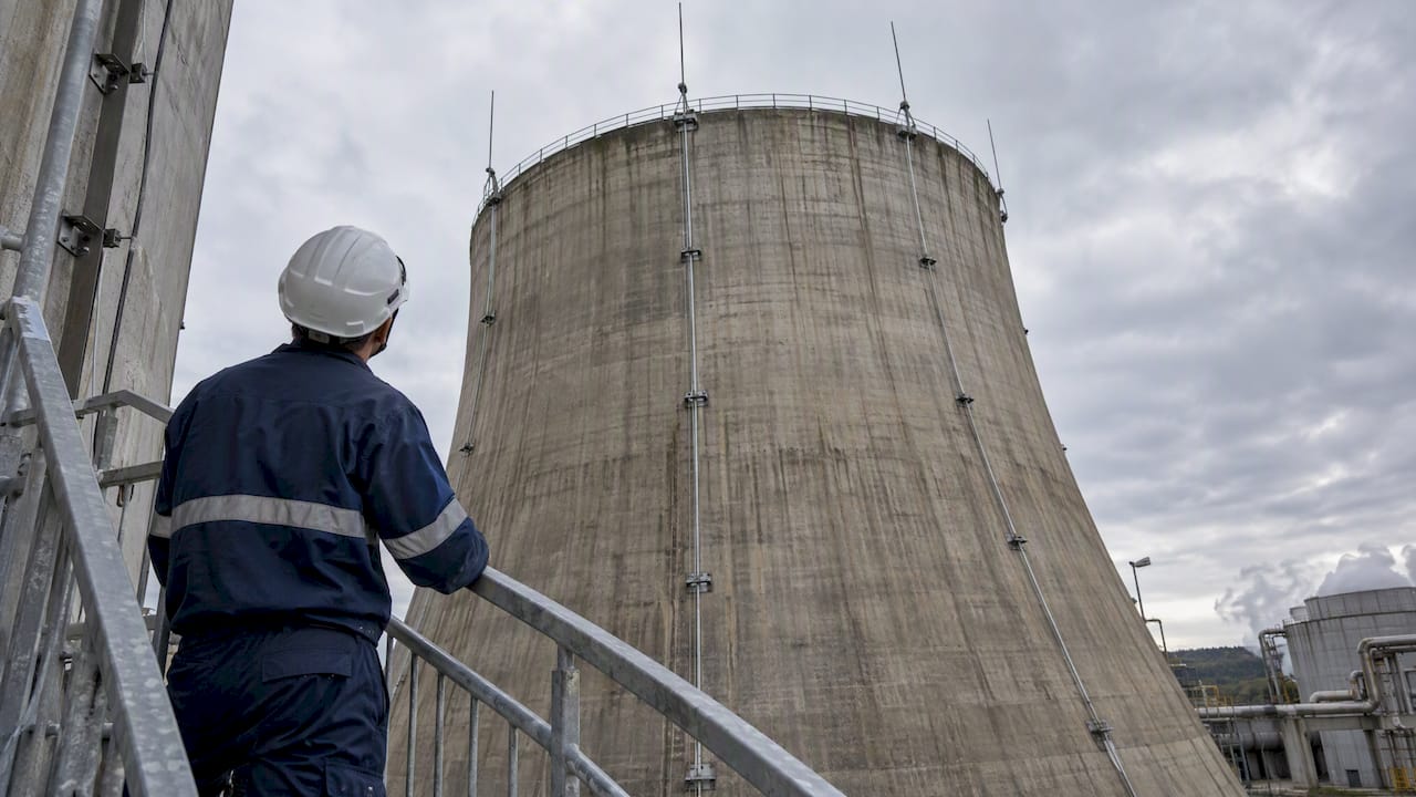
Air terminals, or paratonnerres, intercept the strike before it reaches the structure. On tall, open-shell towers, a single mast rarely covers the geometry well. Engineers typically specify a distributed termination network with multiple capture points tied together, which spreads current paths and reduces mechanical stress at any one connection.
Downconductors carry that current to ground. On a cooling tower, they face constant vibration, water spray and temperature cycling, so routing and fixation matter as much as conductor size.
Equipotential bonding ties metal items, ladders, platforms, piping and structural steel, into the same electrical reference so a strike doesn’t create a dangerous voltage difference between two points a worker might touch at once. Inside enclosed sections or sensitive control rooms, a mesh or Faraday-cage approach extends that protection to equipment that can’t tolerate induced surges.
- Air terminals intercept the strike and must be sized to the tower’s height and shell geometry.
- Downconductors route current to earth and need mechanical fixation rated for vibration and corrosion.
- Equipotential bonding links metal items to prevent dangerous potential differences.
- Mesh or cage systems protect enclosed or instrumented areas from induced effects.
Pro Tip:Treat every bonding point as a future inspection point: if a clamp can’t be reached safely during a biennial check, it will eventually get skipped.
What standards and regulations require for cooling tower protection
French regulatory texts and European standards work together, and treating them as separate checklists is where most projects lose time.
NF EN IEC 62305-2 is the normative reference for lightning risk evaluation. It defines how to calculate the required protection level for a given structure and what that level means for component selection. This is the standard the ARF is built on, not a separate option.
On the regulatory side, installations classified under certain ICPE rubrics can be ordered to implement protections based on a site-specific risk analysis, and that analysis must be updated after any substantial modification to the installation. When a strike is actually recorded on-site, the same texts set deadlines for verification, often within one month for a visual check, with prompt repair of anything found damaged.
- The ARF, built on NF EN IEC 62305-2, sets the protection level and drives all downstream design choices.
- ICPE classification can trigger mandatory protection measures and periodic reporting obligations.
- Documentation, including verification notices and maintenance records, must be retained and updated after changes or recorded strikes.
Our lightning standards overview maps these texts to the deliverables a technical study should actually produce.
Commissioning the ARF and technical study (ET): inputs and outputs
A well-scoped ARF and technical study give you something concrete to evaluate, not just a compliance stamp. Knowing what goes in and what should come out helps you write a tender that gets you a usable design rather than a generic report.
- Site geometry and exposure: tower height, shape, surrounding structures and local lightning density feed directly into the risk calculation.
- Grounding and soil data: existing earth network layout and soil resistivity influence the recommended electrode scheme.
- Process criticality: fans, motors, chemical dosing pumps and control systems whose failure would cause downtime or environmental exposure should be flagged explicitly.
- ICPE status: classification under the relevant rubric can add obligations the ET must address directly.
- Deliverables: the completed ET should specify the chosen protection level, the capture system design, the grounding scheme, a schedule of surge protection devices, and a verification and maintenance plan.
The ARF isn’t a one-time document. It should be revisited after a major structural modification, an extension of process equipment, or a recorded strike that suggests the original risk profile has shifted.
Designing and placing protection on a cooling tower structure
Cooling towers present a specific design problem: tall, often open, metal or concrete shells exposed to constant moisture, with awkward access for both installation and later maintenance.
Air terminal siting has to account for the tower’s full silhouette, not just its highest point. On wide, open shells, a roof-mounted mesh network paired with several masts around the perimeter typically outperforms a single central rod, because it keeps individual conductors shorter and current paths more predictable. The choice between masts and a roof network should be justified in the ET with a calculation of likely current distribution, since a single concentration point creates both a mechanical and an electrical weak spot.
Conductor sizing has to allow for the environment, not just the current rating on a datasheet. Spray, humidity and constant vibration from fan units accelerate wear at every mechanical joint, so corrosion-resistant materials and fastenings that can be re-torqued without replacement are worth specifying up front.
- Site air terminals around the tower’s full perimeter, not just its highest point, to shorten current paths.
- Choose corrosion-resistant conductor materials and fastenings rated for constant vibration and spray.
- Bond ladders, platforms, pipework and access points into the same equipotential system as the main structure.
- Route downconductors away from walkways where mechanical damage or accidental contact is likely.
Pro Tip:Document clamp torque values at installation. It gives your maintenance team a baseline to check against during the next verification instead of guessing whether a connection has loosened.
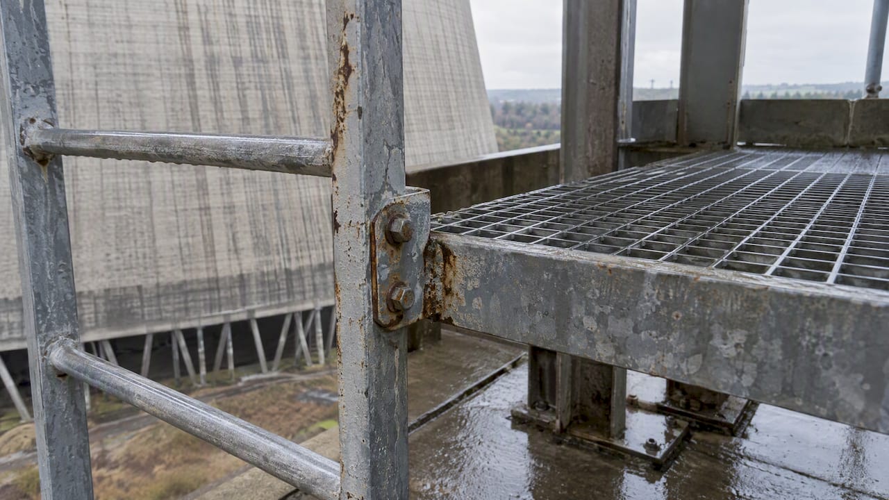
Practical bonding at access points deserves particular attention. A ladder or platform that’s electrically isolated from the main bonding network, even by a coat of paint or a rusted bolt, turns into a hazard the moment current needs to travel through it.
Surge protection for the electrical systems around a cooling tower
External lightning protection stops a direct strike from damaging the structure, but it does nothing to shield motors, variable frequency drives and control cabinets from the surges that travel in on power and signal cables. That’s where coordinated surge protection devices (SPDs) come in.
Fans, pumps, VFDs, sensors and control panels are the equipment most exposed, since they sit closest to both the external protection system and the facility’s internal wiring. A coordinated Type 1/Type 2/Type 3 approach places the heaviest-duty SPDs at the main switchgear, a second tier at distribution boards, and finer protection at local control panels closest to sensitive electronics.
- Protect motors, VFDs, control cabinets and sensors, the equipment most exposed to induced surges.
- Use a coordinated Type 1/Type 2/Type 3 arrangement from main switchgear down to local panels.
- Bond every SPD properly to the earthing network so it has a clean path to dissipate energy.
- Inspect SPD status indicators during routine visits, since a tripped device offers no protection until replaced.
On sites running sensitive drives, coordinating internal surge protection with the external system in the ET avoids the repeated equipment failures that otherwise get blamed on bad luck. Our surge protection range covers this coordination from main incomers down to local panels.
Grounding and earth network design for cooling tower sites
A lightning protection system is only as effective as the ground it discharges into, and cooling towers often sit on large industrial sites where the earth network already serves other equipment.
A low-impedance network, typically built from deep electrodes or ring conductors tied into the site’s main earthing system, gives the strike current a fast, predictable path to ground, as explained in risks and protections for solar panels. On sites with high soil resistivity, deep electrodes often outperform a simple ring because they reach more conductive soil layers below the surface.
Managing touch and step potentials matters wherever people walk near the base of the tower or its grounding points. Bonding the tower’s network to the facility’s main earthing system, rather than leaving it as an isolated loop, reduces the risk of a dangerous voltage gradient appearing at the boundary between the two.
- Favor deep electrodes or ring conductors tied into the main site earthing system for low impedance.
- Bond the tower’s earth network to the facility’s main system rather than isolating it.
- Retest earth resistance on a cadence tied to the full verification schedule, not separately.
- Account for soil corrosion and seasonal moisture variation when selecting electrode material and depth.
Industry practice calls for annual visual inspections and a full verification every two years, with qualified professionals performing the checks on higher protection levels. That cadence applies directly to grounding continuity, not just the visible capture system.
Installation, verification and maintenance: the schedule that keeps protection valid
A lightning protection system that’s installed correctly but never checked again is a liability waiting to surface, usually after the strike that was supposed to be the test.
- Initial verification: a complete check should happen within six months of installation, confirming every connection matches the ET before the system is considered accepted.
- Annual visual inspection: a yearly walk of the capture system, conductors and visible bonding points catches obvious damage, corrosion or loosened fixings early.
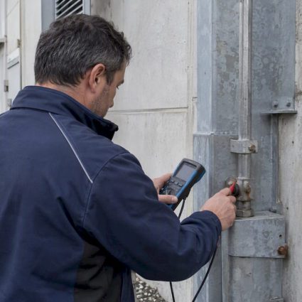
- Full verification every two years: this includes continuity testing at every joint, since mechanical loosening from vibration is a common cause of lost continuity on structures like cooling towers.
- Post-strike checks: after a recorded strike, affected devices need prompt verification, with repairs completed on the timeline set by the applicable arrêté.
Large installations illustrate this in practice: top-of-tower inspections at facilities like Golfech run on a two-year cadence, checking both conductor continuity and the physical condition of capture devices.
Every verification should produce a notice documenting what was checked, what was found and what was corrected, filed alongside the carnet de bord that tracks the system’s full history.
Pro Tip:Keep the carnet de bord with the facility’s other regulatory binders, not in a separate lightning-protection file. It gets updated more reliably when it’s part of the routine maintenance walk.
Quick-spec checklist for design review and handover
A short list to keep on hand when reviewing a proposal or signing off on a completed installation.
- Require the ARF, the ET, a grounding sketch, an SPD schedule and a verification notice as design deliverables.
- Request measured earth resistance values and continuity readings at handover, not just a sign-off letter.
- Check corrosion-resistant fixings and torque documentation on every downconductor clamp.
- Confirm the annual and biennial inspection dates are scheduled before the installer leaves site.
| Checklist item | When to request it |
|---|---|
| ARF and ET deliverables | At design review, before installation starts |
| Grounding sketch and SPD schedule | At design review and handover |
| Measured earth resistance and continuity | At handover |
| Annual visual inspection | Every year |
| Full verification with continuity testing | Every two years |
Why work with a qualified lightning protection specialist
Designing a cooling tower’s protection system means weighing structural geometry, process criticality and local soil conditions at once, which is why the ARF and ET are normally commissioned rather than assembled from a template.
We’ve been working in lightning protection since 1955, with a dedicated R&D center and project experience across industrial sites worldwide. A specialist engagement should produce the ARF, the ET, a full execution dossier, verification reports and a carnet de bord, documents that outlast the original installation team and give the next maintenance manager something to work from.
That documentation matters more than the hardware itself once the system has been in place for a few years, since it’s what proves the protection still matches the site’s actual risk.
Balancing safety, uptime and lifecycle costs
The temptation on any cooling tower project is to treat lightning protection as a one-time capital expense. That thinking misses where the real cost shows up later: a loosened clamp that fails continuity testing, a grounding point corroded past usefulness, a surge that takes out a VFD because the SPD coordination was never specified.
Verified grounding and disciplined clamp practice cost little next to an unplanned shutdown. Folding lightning checks into the existing preventive maintenance calendar, rather than running them as a separate annual event, is usually what makes the difference between a system that gets inspected and one that gets forgotten.
— INDELEC
How we help design, install and maintain cooling tower protection
Getting the ARF right at the start saves rework later, and that’s the piece of this work we spend the most time on. Our lightning protection services cover the full sequence: risk analysis and technical study, installation, grounding, surge protection coordination, and verification and maintenance on the cadence your site actually needs.

Combining the tasks of risk analysis, installation, and verification under a single scope helps keep documentation consistent from design through the first biennial check. If your cooling tower hasn’t had a site-specific risk analysis, or if the last verification is more than two years old, that’s the place to start.
Request a site assessment through our protection contre la foudre services page and we’ll scope the ARF, the ET and a maintenance schedule built around your tower’s actual exposure.
FAQ
What is the best protection against lightning for a cooling tower?
The most reliable approach combines a site-specific risk analysis under NF EN IEC 62305-2 with a matched system of air terminals, downconductors, bonding, grounding and coordinated surge protection. No single component qualifies as complete protection on its own; the ARF determines which combination fits the specific structure.
What regulations apply to lightning protection in France?
Lightning protection is governed by arrêtés tied to the ICPE classification system alongside the European standard NF EN IEC 62305-2. Installations under certain ICPE rubrics can be required to carry out a risk analysis and implement specific protection measures, with documentation retained and updated after major changes.
What makes up a lightning protection system?
A complete system includes air terminals to intercept the strike, downconductors to route current to ground, equipotential bonding to prevent dangerous voltage differences, a low-impedance earth network, and surge protection devices for connected electrical equipment. Each piece is specified in the technical study (ET) that follows the initial risk analysis.
What preventive measures reduce lightning risk at an industrial site?
Preventive measures include commissioning an ARF to identify site-specific exposure, maintaining a documented annual and biennial inspection schedule, and keeping bonding and grounding connections in good repair. Industry guidance recommends annual visual inspections with a full verification every two years, performed by a qualified professional for higher protection levels.
How often should a cooling tower’s lightning protection be inspected?
A full verification, including continuity testing at every joint, is recommended every two years, with a visual inspection in between on an annual basis. Large facilities such as the Golfech cooling towers follow this same two-year cadence for top-of-tower checks.
Sources
- Arrêté (Legifrance) — dispositions relatives à la protection contre la foudre
- AFNOR boutique — NF EN IEC 62305-2
- Bureau Veritas — protection des installations contre la foudre
- EDF — Au sommet des tours aéroréfrigérantes (Golfech)