Prevent Lightning Induction: 5 IEC Measures for Facility Managers
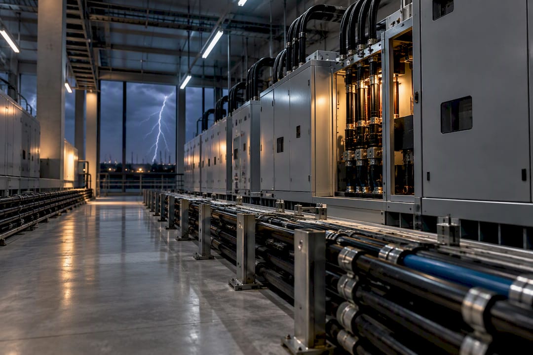
Mitigating lightning-induced induction requires site-wide equipotential bonding and an earthing mesh, LPZ zoning with coordinated surge protective devices, and disciplined cable routing and shielding. A single parafoudre installed at the service entrance cannot compensate for poor equipotentiality or oversized wiring loops. The reference framework is the IEC 62305 series alongside IEC 61000-4-5, backed by a formal Analyse du Risque Foudre (ARF) and study technique (ET).
TL;DR:
- Proper lightning mitigation demands a comprehensive system including site-wide bonding, meshed earthing, zoning, and coordinated surge protectors, not just a single device.
- Inductive coupling is the primary cause of induced voltages, which scale with loop area, making cable routing and shielding critical for effective protection.
- Conducting a risk analysis and detailed study—ARF and ET—before installation ensures the protection scheme is tailored and effective, preventing underperformance.
- Regular testing, including after lightning strikes, soil resistivity checks, and SPD functionality assessments, is essential to maintain protection integrity over time.
- Field experience guides optimized grounding and SPD sizing, emphasizing the importance of cohesive design and ongoing verification over standard compliance alone.
Table of Contents
- What Causes Lightning Induction in Electrical Systems?
- Core Measures for Reducing Induced Lightning Currents
- How Do You Design and Implement a Mitigation Plan?
- Special Cases: Photovoltaics, Antennas, and EV Chargers
- How Often Should Lightning Protection Systems Be Tested?
- Why Field Experience Changes SPD and Grounding Decisions
- What Facility Managers Get Wrong About Induction Protection
- Commission an ARF, ET, and Full Lightning Protection Program
- Sources
- FAQ
What Causes Lightning Induction in Electrical Systems?
A lightning electromagnetic pulse, or LEMP, doesn’t need a direct strike to damage equipment. Direct strikes, nearby strikes on structures or lines, and even flashes several kilometers away all generate transient fields that couple into conductors through four distinct mechanisms: capacitive, inductive, galvanic, and radiated coupling.
Inductive coupling deserves the most attention from designers because it scales directly with loop area. A cable running in a tight bundle with its return path induces far less voltage than the same cable routed on the opposite side of a room from its neutral. The induced voltage is proportional to the rate of change of magnetic flux through that loop, so a wide loop during a fast-rising lightning current produces a correspondingly large transient, even if the strike itself lands hundreds of meters away.

Galvanic coupling occurs when structures share a common earth path and a strike raises local ground potential, pushing current back through bonding conductors into electronics. Radiated coupling affects longer runs of cable acting like antennas. These distinctions matter because they produce different damage signatures: common-mode surges tend to stress insulation and cause dielectric breakdown, while differential-mode surges deliver energy that overheats components. Equipment-level immunity testing under IEC 61000-4-5 verifies how a device withstands a defined surge waveform, but it does not replicate a direct lightning current injection, so passing that test says nothing about how the same device behaves once installed in a building with long cable runs and shared earths.
Core Measures for Reducing Induced Lightning Currents
Every mitigation program rests on five interlocking measures, and skipping any one of them undermines the rest. IEC 62305-4 frames this explicitly: combining equipotential bonding, meshed grounding, zoning, cable discipline, and coordinated SPDs is what actually reduces induced voltages, not any single component.
- Equipotential bonding: tie every metallic mass, cable screen, structural steel member, and service entry point into the same bonding network so nothing floats at a different potential during a transient.
- Meshed earthing: build a mesh rather than isolated ground rods; separate earths for different systems (telecom, power, structural) create the very potential differences you’re trying to eliminate.
- LPZ zoning: define Lightning Protection Zones so exposure drops in steps from the building perimeter inward, placing equipotential links or isolating interfaces at each boundary.
- Coordinated SPDs: install surge protective devices at zone boundaries and equipment entries, sized and coordinated with attention to
Iimp,In, andUp, since a high residual voltage downstream of an undersized SPD still damages sensitive electronics. - Cable routing and shielding: minimize loop area, maintain continuous metallic cable paths for screen termination, and substitute fiber optic links where galvanic isolation is the more practical fix.
Pro Tip:Before specifying SPD ratings, model the downstream wiring geometry. A device with an excellent Up rating on paper can still let dangerous residual voltage reach equipment terminals if the conductor between the SPD and the load is too long or poorly routed.
For sites where downtime isn’t an option, temporary preventive measures tied to a thunderstorm warning system can reduce specific risk components while permanent works are scheduled, a point IEC 62305-2 addresses directly in its risk framework.
How Do You Design and Implement a Mitigation Plan?
Translating the checklist above into a buildable system follows a defined sequence, and skipping steps is where most induction problems originate.
- Run the ARF. The Analyse du Risque Foudre, based on IEC 62305-2, sets the required protection level using ground contact point density (NSG) and damage-frequency metrics. For classified or regulated installations, French regulatory texts require this analysis before any equipment gets specified, and the output determines everything downstream, including whether temporary preventive measures are justified.
- Produce the study technique (ET). This document specifies exact SPD models and locations, the coordination plan between cascaded devices, earthing mesh layout drawings, and cable routing diagrams. It is the engineering deliverable a contractor should bid against, not a general recommendation.
- Set LPZ boundaries and SPD locations. Match each zone transition to the withstand level of the equipment inside it. A data closet needs a tighter zone than a loading dock, and the SPD selected at that boundary should reflect it.
- Detail bonding points and conductor sizing. Specify exact screen termination technique at every gland, and require equipotential bonding plates at cable and pipe penetrations, since penetrations are where inconsistent bonding most often slips through.
- Build in test points and instrumentation. Include lightning strike counters and clear acceptance criteria for the initial verification, so the commissioning team has objective pass/fail thresholds rather than a visual sign-off.
This sequence mirrors how Indelec structures its own lightning protection services, moving from risk analysis through installation to verification rather than treating any single stage as sufficient on its own. Cutting straight to SPD purchase without the ARF and ET steps is the single most common reason induction mitigation projects underperform once installed, because the coordination between devices and the mesh was never actually engineered.
Special Cases: Photovoltaics, Antennas, and EV Chargers
Standard mitigation rules need adaptation for a few recurring installation types where geometry or interconnection is unusual.
- Photovoltaic arrays: induced currents travel along DC strings and can reach inverters directly, so string combiner boxes and inverter entries need dedicated equipotential bonding and PV-rated SPDs sized for the array’s current-sharing behavior under a strike, a scenario IEC 62305-4’s revised annexes now address in more detail.
- Telecom and antenna penetrations: coaxial feeds need isolating interfaces or surge filtering at the building entry point, correct coax termination, and, where applicable, quarter-wave stub grounding to shunt transient energy before it reaches receiver electronics.
- EV charging infrastructure: both the supply side and the onboard charger electronics need protection, with SPDs coordinated across the charging point and upstream distribution board. For fleet depots, event logging tied to the charger controller helps operators correlate outages with recorded lightning activity rather than guessing at a cause.
How Often Should Lightning Protection Systems Be Tested?
Verification isn’t optional paperwork. It’s the only way to confirm a mitigation system still works after soil conditions shift, cable routes get modified, or a strike actually occurs. French regulation prescribes a specific cadence: initial verification by a competent body after installation, annual visual inspections, and a full verification every two years.
- Check continuity of every equipotential bonding connection, not just the main earthing conductor.
- Measure soil resistivity periodically, since seasonal moisture changes can shift earthing performance more than most engineers expect.
- Confirm SPD function through their status indicators and, where accessible, spot-check residual voltage at critical equipment terminals.
- After any recorded strike, run a simplified verification promptly, and escalate to a full verification if that check reveals damage or drift in earthing values.
Every inspection, remedial action, and recorded strike belongs in the site’s carnet de bord (logbook), because the regulatory framework ties compliance directly to that record and an insurer or auditor will ask for it after an incident, not before.
Why Field Experience Changes SPD and Grounding Decisions
Standards define the framework, but coordinating an SPD cascade correctly, sizing an earthing mesh for difficult soil, and choosing strike-recording instrumentation that actually holds up in the field come from doing the work repeatedly. A company with decades of experience in lightning protection operates an R&D center that tracks how IEC 62305-4’s evolving guidance on induced voltages plays out in real installations, from industrial sites to data centers.
That accumulated project history, spanning international lightning protection work, shapes decisions that a standard alone can’t dictate: which mesh geometry suits a given soil resistivity, where a deep-earth electrode outperforms a shallow mesh, and how to select instrumentation that survives years of field exposure. If your site needs an ARF or ET, that’s the starting conversation.

What Facility Managers Get Wrong About Induction Protection
The most expensive mistake isn’t a missing SPD. It’s separate earths for telecom, power, and structural steel, which guarantees potential differences during a strike no matter how good the individual devices are. Close behind: cable trays routed with wide loop areas between a system and its return path, and a single SPD at the main panel treated as a complete solution while sub-distribution boards sit unprotected.
The fix is rarely expensive once identified: bond the earths into one mesh, tighten cable routing, and add coordinated SPDs downstream. Pair permanent measures with a thunderstorm warning system for operations that can’t tolerate unplanned downtime, and use that warning window for temporary preventive actions while the storm passes.
— INDELEC
Commission an ARF, ET, and Full Lightning Protection Program
The advantage of experienced lightning protection providers over general electrical contractors is straightforward: the workflow described in this article—ARF, ET, installation, verification, and maintenance—is supported by extensive international project experience rather than assembled for a single job.

Indelec’s lightning protection services cover the full lifecycle: the risk analysis that sets your protection level, the technical study that specifies every device and bonding point, installation, and the recurring verification cadence regulation requires. If your facility handles photovoltaic arrays, telecom penetrations, or an EV charging depot, that same pathway applies with the adapted measures this guide covers. Explore the full services overview or reach out directly to request a site survey and ARF for your installation.
Sources
FAQ
What Is the 50cm Rule for Surge Protective Devices?
The rule refers to keeping the total conductor length connecting an SPD to the protected circuit as short as possible, since longer leads add inductance that raises the residual voltage reaching equipment. When practical limits are exceeded, coordinated SPDs or a cascaded protection scheme downstream compensate for the added lead length.
What Device Protects a Building Against Lightning?
No single device provides complete protection. A lightning rod or air termination system intercepts a direct strike, while equipotential bonding, an earthing mesh, and coordinated surge protective devices at zone boundaries handle the induced currents a strike generates elsewhere in the building, as IEC 62305-4 outlines.
What Is the Best Protection Against Lightning?
The most reliable approach combines several measures rather than relying on one: equipotential bonding, meshed grounding, LPZ zoning, disciplined cable routing, and coordinated SPDs sized against equipment withstand levels. Indelec builds this combination into its ARF and ET process so each site gets a protection level matched to its actual risk rather than a generic setup.
Should You Unplug Devices During a Thunderstorm?
Unplugging sensitive electronics during a storm can help in buildings without coordinated surge protection, since it removes a direct path for induced transients on unprotected circuits. In a properly protected facility with coordinated SPDs and equipotential bonding in place, this manual step becomes far less critical because the system is designed to handle the surge automatically.
How Often Does a Lightning Protection System Need Verification?
Regulation requires an initial verification after installation, annual visual inspections, and a full technical verification every two years. After any recorded lightning strike, a simplified verification within one month is required, with a full check and remedial actions logged if that inspection finds damage.