Why Single Earth Rods Fail for Coastal Boats and Floating Homes
Do not rely on a single earth rod driven into sand. It rarely delivers a safe, stable ground at the coast, and it is not what protective earthing standards intend. The correct approach depends on your scenario: equipotential bonding tied to shore power for boats, a shore-connected earth or an engineered floating-earth system with reinforced protections for floating homes, and strict adherence to standards like IEC/IEEE 80005-1 for any shore-to-vessel connection. All of it needs professional resistivity testing and materials chosen to survive salt.
TL;DR:
- Relying on a single earth rod in coastal sand often results in high resistance that compromises protection, requiring engineered grounding solutions instead.
- Saltwater conductance can cause corrosion, stray currents, and false fault signals, making proper bonding and verified earth connections essential for safety.
- Proper shore power connection involves a strict sequence of de-energizing, bonding, and testing, with residual current devices and monitoring to prevent faults from causing harm.
- Floating homes require specialized grounding methods, such as shore-connected earth conductors or floating-earth systems, designed to withstand tidal and salinity effects.
- Regular testing, site-specific resistivity surveys, and materials like tinned copper and grade 316L stainless steel are critical to maintaining coastal grounding integrity over time.
Table of Contents
- Why Coastal and Marine Environments Change Grounding Behavior
- Grounding and Bonding for Small Craft and Pleasure Boats
- Grounding Solutions for Floating Homes and Permanently Moored Structures
- Shore Power, High-Voltage Shore Connections, and Standards to Follow
- Materials, Installation Techniques, and Corrosion Mitigation for Coastal Earthing
- Testing, Verification, and Maintenance Schedule for Coastal Grounding
- Safety Rules, Legal Notes, and Applicable Electrical Regulations
- Indelec’s Perspective: Why Professional Assessment Changes the Outcome
- The Editorial Take: What Actually Matters at the Shoreline
- Get a Site Survey Before You Guess at a Coastal Ground
- Standards and Guidance Worth Reading Directly
- Sources
- FAQ
Why Coastal and Marine Environments Change Grounding Behavior
Sand behaves nothing like ordinary inland soil when it comes to conducting electricity. Dry beach sand can have resistivity in the thousands of ohm meters, while a typical inland clay soil sits in the tens or low hundreds. That gap matters because earth resistance depends directly on the resistivity of the ground around the electrode. Drive a rod into loose, well-drained coastal sand and you can measure resistance high enough to make a protective earth practically useless.
Seawater complicates the picture rather than solving it. Saltwater conducts well, which tempts people into treating the ocean as a convenient, infinite earth. It is not a safe automatic ground for protective earthing. Immersing a bare conductor in seawater invites galvanic corrosion between dissimilar metals, and it can create stray direct currents that travel along hull fittings, propeller shafts, and underwater metalwork on neighboring boats. A forum-documented case recorded a shallow rod in sandy coastal ground returning very high resistance, far above any workable threshold for a protective earth.
The practical consequences show up in ways owners notice long before they understand the cause:
- Residual current devices that trip randomly or fail to trip at all when they should
- Corroded, chalky white deposits forming around buried or submerged terminations within a season or two
- Metal fittings on a boat or dock losing thickness unevenly, a classic sign of stray-current or galvanic activity
- Earth resistance readings that climb noticeably between one inspection and the next, rather than staying flat
Salinity and moisture cut two ways here. Wetter, saltier ground conducts electricity more easily, which can lower measured resistance in the short term. That same salinity accelerates corrosion of the electrode and its connections, so the system that tests fine this year can fail within a few years as metal degrades underground. Anyone grounding near saltwater is fighting two opposing forces at once, and a design that only accounts for one of them will eventually fail.
Grounding and Bonding for Small Craft and Pleasure Boats
Protective earthing and equipotential bonding are not the same thing, and confusing them is where most boat electrical problems start. Protective earthing carries fault current back to a source and clears a breaker. Equipotential bonding does something different: it ties together all the metal parts on a boat, from the engine block to the shore power inlet ground pin, so that everything sits at the same electrical potential. On a vessel floating in water, bonding is what keeps a fault on one appliance from turning the whole hull into a shock hazard.
That distinction becomes critical the moment you plug into shore power. A boat is not fixed to the earth the way a house is, so its safety depends on that bond to the shore system being intact, low resistance, and continuous. The IRCLASS guidelines on earthing systems for ships lay out equipment-earthing conductor requirements and periodic testing precisely because a broken bond on a floating vessel is far more dangerous than the same fault on a building slab.
Connecting to shore power safely follows a specific order, and skipping steps is where accidents happen:
- Confirm the shore power source is de-energized before touching any connections.
- Attach the equipotential bonding strap or ground conductor first, before any power conductor makes contact.
- Seat the shore power connector fully and confirm any safety interlock has engaged.
- Energize the circuit only after the bond and interlock are confirmed.
- To disconnect, reverse the order: de-energize first, then break the power connection, and remove the bonding strap last.
That sequence exists so the hull is never live without a path to ground, and never grounded without a completed circuit that a fault could exploit.
A few protective measures are not optional extras:
- A 30 mA residual current device on the shore power circuit, sized to trip fast enough to prevent injury from a fault current path through a person in water.
- Marina-side earth monitoring where the dock infrastructure supports it, since a fault on a neighboring berth can affect your bonding if the shared earth degrades.
- Regular visual inspection of the shore cable, connector pins, and bonding strap for corrosion, since these parts see constant wet and dry cycling.
An immersed copper rod or plate hanging off the stern is not a substitute for any of this. It looks like a ground connection, but without engineered bonding to the rest of the boat’s metalwork and a verified path back to the shore system, it does nothing for fault protection and actively invites galvanic corrosion between the copper and your underwater hardware.
Pro Tip:Before you assume your boat’s bonding is fine, ask the marina operator what their shore earth infrastructure actually looks like. A bonding system that is flawless on your boat still fails if the dock’s own earth reference is degraded or poorly maintained.
Grounding Solutions for Floating Homes and Permanently Moored Structures
A floating home is legally and technically closer to a building than to a boat, and that distinction drives everything about how it gets grounded. Regulators in France increasingly treat permanently moored floating homes as buildings for electrical purposes, which means the same NF C 15-100 standard that governs a house on land can apply to a stationary floating structure, even though the structure itself sits on water rather than a foundation.
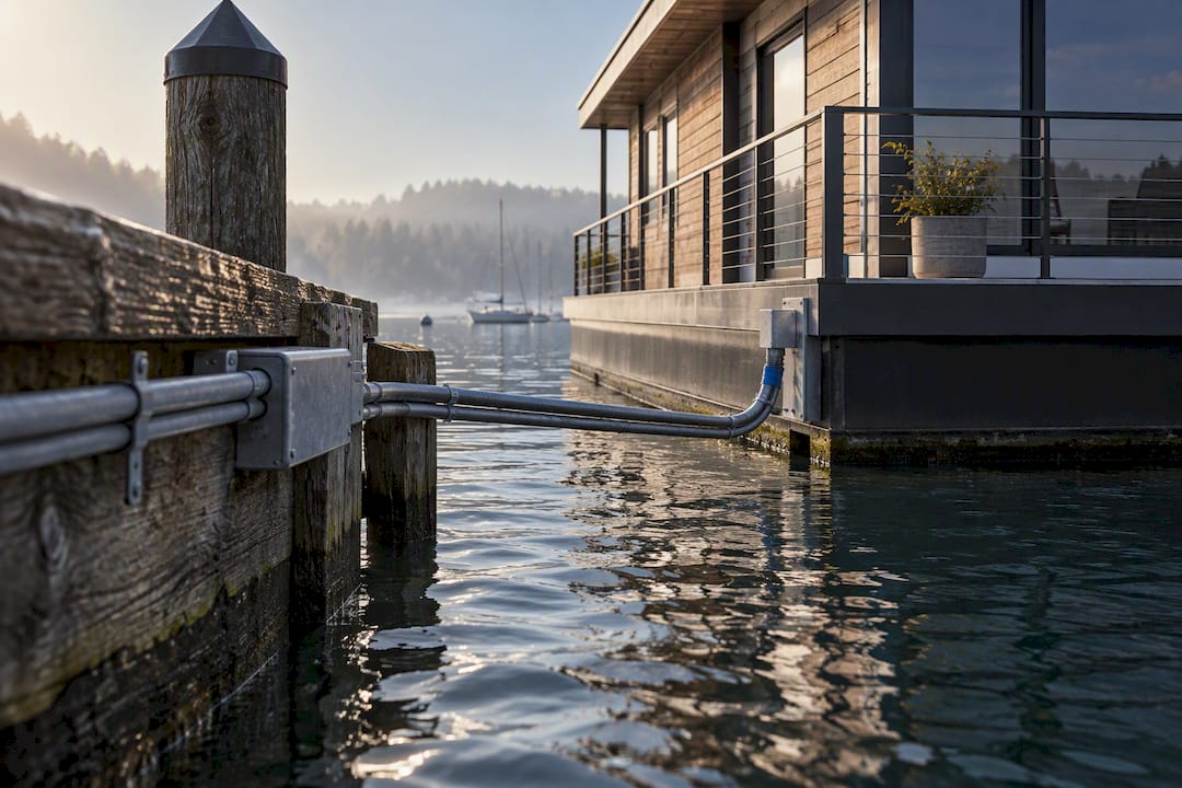
Promotelec’s guidance is direct on this point: a floating home cannot use a conventional earth rod the way a land-based house does, since there is no stable soil to drive it into. The two accepted alternatives are a shore-connected earth, where a dedicated earth conductor runs from the structure back to a verified earth point on land, or a floating-earth system built with reinforced protective measures designed specifically for the electrical isolation a floating structure creates.
Each option carries its own installation demands.
Shore-connected earthing means running an earth conductor alongside the shore power feed, sized and routed to avoid mechanical stress from wave action, tidal rise and fall, and seasonal water level changes. The conductor needs slack built into its run, protected conduit at every point where it crosses from fixed dock to floating structure, and a termination on land that itself meets standard earth resistance targets.
Floating-earth systems work without a physical tether to land soil, instead relying on layered protective devices, such as isolation transformers or enhanced residual current protection, to compensate for the absence of a direct earth reference. These systems demand more rigorous design and more frequent verification, because there is no simple continuity check back to a fixed point.
Whichever route applies, a few practicalities determine whether the system holds up over years rather than months:
- Route the equipotential bonding conductor to avoid chafing points where the structure moves against its mooring or dock connection.
- Protect every penetration point where a conductor passes through a hull, deck, or floating platform wall, since these are where water intrusion starts.
- Keep documentation of the earth conductor route, termination points, and test results, since inspectors and insurers will ask for it.
- Schedule a formal inspection at installation and after any major structural or dock modification, not just on a fixed calendar.
Getting this wrong is not a minor code violation. A floating structure with a failed or absent earth reference can leave every metal fixture in the home live relative to the water around it, which is a direct shock hazard for anyone in or near the water.
Shore Power, High-Voltage Shore Connections, and Standards to Follow
For any vessel or structure connecting to shore power, IEC/IEEE 80005-1 sets the technical baseline the rest of this article’s recommendations build on. The standard requires equipotential bonding between the shore side and the vessel or structure side of the connection, mandates continuous monitoring of that bond, and specifies a maximum touch and step voltage of 30 volts, with a safety loop required to open within 200 milliseconds if that threshold is exceeded.
That last figure deserves attention because it explains the entire design philosophy behind shore power safety systems.
A 30-volt limit and a 200-millisecond window define how fast a fault has to be cleared. IEC/IEEE 80005-1 sets touch and step voltage at a 30-volt ceiling specifically because that is roughly the threshold below which a fault current path through a human body in wet conditions is unlikely to cause cardiac injury. The interlock and monitoring systems exist to guarantee that ceiling is never exceeded for longer than that window allows.
Neutral grounding resistors, or NGRs, play a central role in high-voltage shore connection (HVSC) systems used for larger vessels and industrial berths. An NGR limits fault current magnitude, which protects equipment, but sizing it involves a real trade-off: higher resistance reduces fault current but can increase clearance time and raise touch voltage during a fault, according to technical analysis of NGR design in shore power systems. Getting that balance wrong defeats the purpose of the resistor entirely.
Most private boat owners will never touch an HVSC system. Typical marina low-voltage (LV) shore power connections operate at standard domestic or light commercial voltages and rely on simpler bonding and RCD protection rather than NGR-based fault management. Still, the underlying principle carries over directly:
- Bonding must be continuous and verified, not assumed, every time a connection is made.
- Interlocks that prevent energization before bonding is confirmed are not a formality, they are the actual safety mechanism.
- Any monitoring system detecting a bonding failure should cut power automatically, not just alert someone to investigate later.
- Touch voltage limits apply at LV scale too, even though the numbers involved are smaller and the consequences feel less dramatic until something goes wrong.
The common thread across HVSC and marina LV systems is that monitoring and automatic disconnection are not optional add-ons. A shore connection that bonds correctly on day one but has no way to detect a broken bond on day two hundred is a system waiting to fail quietly.
Materials, Installation Techniques, and Corrosion Mitigation for Coastal Earthing
Standard galvanized steel rods, common in ordinary land grounding, do not belong anywhere near saltwater or salt-laden coastal soil. Coastal installation data from Mayterio recorded old galvanized rods at coastal sites measuring over 400 ohms of earth resistance, a direct result of accelerated corrosion eating away the electrode’s effective surface area over time.
The materials that actually hold up:
- Tinned copper conductors and rods, which resist the chloride-driven corrosion that attacks bare copper and steel alike near salt spray and saline groundwater.
- Stainless steel, specifically grade 316L, for hardware, clamps, and fasteners exposed to splash zones or buried in saline soil, since standard 304 stainless corrodes noticeably faster in chloride-rich environments.
- Protected, sealed terminations at every connection point, because a corroded connection point often fails before the conductor itself does.
Installation geometry matters as much as material choice. A single vertical rod concentrates current into a small volume of soil right around its tip, which is exactly the wrong strategy in sandy ground where resistivity is already working against you. Horizontal trench earthing, where a conductor runs buried in a shallow trench across a larger area, spreads that current over far more soil volume and typically achieves lower resistance in sandy coastal conditions than a comparable rod. Conductive backfill or bentonite-based additives around the conductor can improve contact further in particularly dry or loose sand, though a qualified installer needs to verify the product is compatible with the metals used.
Any earthing hardware sitting in a zone affected by tides, wave action, or fluctuating water tables needs mechanical protection, not just electrical protection. Conduit, cable armor, or physical shielding at the point where a conductor transitions from buried to exposed prevents abrasion damage that would otherwise go unnoticed until a resistance test flags a problem.
Sacrificial anodes, typically zinc or aluminum alloy, are worth mentioning even though they serve a related but distinct purpose. They protect submerged metal hardware from galvanic corrosion by corroding preferentially themselves, and pairing them with a properly bonded and grounded electrical system gives coastal installations two layers of defense against the same underlying threat: saltwater’s relentless appetite for metal.

Pro Tip:Ask your installer for the exact grade of stainless steel used in every fitting, not just the rods. A 316L rod connected with a 304 stainless clamp will still corrode at the weak point, and that weak point is usually the first thing to fail.
Testing, Verification, and Maintenance Schedule for Coastal Grounding
Earth resistance is measured with a tellurometer, an instrument that injects a known test current into the ground through the electrode and measures the resulting voltage drop to calculate resistance. It is a straightforward test in theory, but the number it returns needs context.

The commonly cited under 100 ohm target is a guideline, not a legal absolute, and coastal conditions are exactly where it needs the most scrutiny. Depending on the protective device sizing and fault current characteristics of a given installation, some systems can operate safely above that figure while others need a lower resistance to guarantee protection within required trip times. When a coastal site consistently tests near or above that guideline despite reasonable effort, the answer is not to accept it, it is to re-engineer the electrode configuration, typically by moving to horizontal trench earthing, deeper electrodes, or conductive backfill rather than adding another shallow rod.
A workable inspection cadence for coastal grounding:
- Visual inspection of exposed conductors, terminations, and bonding straps monthly, or at minimum, at the start and end of each boating season.
- A more thorough annual check that includes tightness of connections, visible corrosion signs, and continuity of bonding straps.
- Full earth resistance testing with a tellurometer every two to three years in typical coastal exposure, and annually in particularly harsh conditions like exposed rock coastlines or high wave action zones.
- Immediate re-testing after any storm event, dock modification, or visible damage to the electrical infrastructure.
Every test report should record the measured resistance, the date, weather and tide conditions at the time of testing, and a comparison against the previous reading, since a single number in isolation tells you far less than a trend.
Watch for these signs that something needs attention now, not at the next scheduled check:
- Resistance readings climbing steadily across successive tests, even if each individual reading still looks acceptable
- Visible white or green corrosion deposits forming around any grounding hardware or terminal
- Unexplained pitting or metal loss on hull fittings, propeller shafts, or underwater hardware, a possible sign of stray current
- An RCD that fails its test button check or trips without an apparent cause
Safety Rules, Legal Notes, and Applicable Electrical Regulations
Compliance for stationary floating structures in France runs through NF C 15-100, the same standard applied to land-based residential and commercial buildings, and formal sign-off typically involves a Consuel inspection or a qualified local electrical inspector before a connection is authorized. Boats connecting to marina shore power fall under a different practical framework, closer to the vessel-focused earthing guidance from bodies like IRCLASS, combined with the marina’s own shore power standards.
A handful of rules apply regardless of which category you fall into:
- Never improvise a water-immersed protective earth using a rod, plate, or any bare conductor dropped into seawater or a tidal zone. It is not a recognized safe earthing method and introduces corrosion and stray-current risks.
- Always use compliant protective devices, meaning a properly rated RCD at minimum, on any circuit connecting to shore power or serving a floating structure.
- Check shore power compatibility before connecting any vessel or structure to a new marina or dock, since voltage, frequency, and earthing configuration can vary between facilities.
- Treat any bonding or grounding work involving structural penetrations or shore power interfaces as a job for a certified electrical professional, not a weekend project.
When in doubt, the port authority or marina operator can confirm what shore infrastructure is actually in place, and a certified electrician or engineering firm familiar with marine or floating-structure work should sign off on anything beyond routine inspection.
Indelec’s Perspective: Why Professional Assessment Changes the Outcome
Coastal grounding projects tend to expose a common gap: installations that look fine on paper but are not tested against the actual soil, salinity, and corrosion conditions of that specific shoreline. That gap is where a professional workflow earns its keep.
A proper coastal grounding project starts with site resistivity testing, not a materials catalog. That testing determines whether horizontal trench earthing, deep electrodes, or a shore-connected earth configuration fits the ground you actually have, rather than the ground a generic guide assumes. From there, engineered design accounts for tidal variation and corrosion exposure specific to that site, material selection favors tinned copper and 316L stainless where salt exposure demands it, and installation supervision confirms the design gets built the way it was specified, not approximated in the field.
The last piece, scheduled verification, is where most coastal systems quietly fail years after installation looked perfect. Indelec’s technical consulting and maintenance services build that recurring check into the relationship from the start, rather than treating it as an afterthought once resistance readings have already climbed past a safe threshold.
The Editorial Take: What Actually Matters at the Shoreline
The conventional advice on coastal grounding treats it as a materials problem: buy a better rod, use more copper, add another anode. That framing misses the point. The real failures happen because installations get designed to a generic standard and never re-tested against the specific, shifting conditions of a real shoreline. Salinity, tide, and corrosion do not stay constant, and a system that passed its first inspection can fail its third.
If you take one thing from this guide, prioritize testing over materials. A mediocre electrode configuration that gets tested every two years and adjusted when resistance climbs will outperform an expensive installation nobody checks after the first year. Standards like IEC/IEEE 80005-1 exist because bonding failures at the shore are not theoretical. They show up in stray currents on real hulls and real corrosion on real terminations, and the only defense that consistently works is verification, not a bigger rod.
— INDELEC
Get a Site Survey Before You Guess at a Coastal Ground
Coastal grounding is not a project to guess your way through, and the cost of getting it wrong is measured in corroded hardware and shock hazards, not just a failed inspection. Indelec’s grounding services start with a site-specific resistivity assessment rather than a generic materials list, which matters most on sandy or rocky shorelines where a standard rod configuration is unlikely to hold up.

To get a useful quote, have a few things ready: recent photos of the installation site or vessel connection point, a single-line electrical diagram if one exists, and any previous resistance test reports you have on file. For sites where shallow rods have already proven inadequate, Indelec’s deep earth grounding drilling service addresses exactly that problem with engineered electrodes suited to difficult coastal soils. Reach out through the services page to request a site survey and start with a resistivity test rather than another shallow rod.
Standards and Guidance Worth Reading Directly
For readers who want the primary technical language rather than a summary, a few sources are worth going to directly. IEC/IEEE 80005-1 is the governing standard for shore-to-ship connections and covers bonding, monitoring, and touch-voltage requirements in full technical detail. The IRCLASS earthing guidelines offer vessel-specific earthing practices beyond what a shore power standard alone covers. Promotelec’s floating home FAQ is the clearest available guidance on NF C 15-100 applicability for floating residential structures. Beyond these documents, confirm any formal installation with your local port authority and, in France, a Consuel inspection before considering a coastal grounding project complete.
Sources
- Comment réalise-t-on la mise à la terre d’une maison flottante ? | Promotelec
- Guidelines on earthing systems for ships and offshore structures (IRCLASS)
- Installation électrique en bord de mer : mise à la terre et protection différentielle
FAQ
What standards apply to grounding near the shore?
The standards that matter most are IEC/IEEE 80005-1 for shore-to-ship power connections and NF C 15-100 for stationary floating structures treated as buildings. IRCLASS earthing guidelines add vessel-specific bonding and testing requirements for boats connecting to shore infrastructure.
Can you put a ground rod directly in the water?
No. Seawater is not a safe or recognized protective earth, and an immersed rod or plate invites galvanic corrosion and stray-current problems rather than solving a grounding need. The correct approach is equipotential bonding to a verified shore or land earth system, not a submerged electrode.
Is grounding mandatory for boats and floating homes?
Yes, in the sense that any structure connecting to shore power or mains electricity needs functioning protective earthing and bonding to be safe and compliant. Floating homes treated as stationary structures generally fall under NF C 15-100, while boats follow marina shore power requirements and vessel earthing guidelines from bodies like IRCLASS.
Where should the earth connection be placed on a coastal property?
The earth electrode or connection point should sit where soil conditions have been tested and confirmed, not wherever installation is most convenient. On sandy shorelines, horizontal trench earthing spread across a wider soil area typically performs better than a single rod placed near the waterline, and the exact location should follow a resistivity survey rather than a guess.