Earth Resistance Explained: A Guide for Electricians
Earth resistance is the resistance between a grounding electrode system and the general mass of earth — the single figure technicians use to judge whether fault and lightning currents will be safely dissipated into the ground. A high value means dangerous voltages can persist on exposed metalwork during a fault. A low value means the system can channel those currents away fast enough to trip protective devices and keep personnel safe.
Before going further, a practical note: the target values cited throughout this article are industry-referenced benchmarks and engineering targets. They are not universal legal limits. Applicable requirements in France derive from NF C 15-100, NF EN 62305, and related standards — always confirm the specific requirement for your installation type.
Quick takeaways:
- Aim for 5 Ω or less for most grounding systems; lightning protection and sensitive sites often require tighter targets.
- Retest after any system change, severe weather event, or nearby earthworks — and at least once per season to catch worst-case dry-period conditions.
- If measured resistance exceeds your target and remediation (deeper rods, conductive backfill) does not bring it down, call a qualified provider for a soil resistivity survey and engineering assessment.
Key Takeaways
Earth resistance is a dynamic, site-specific measurement that requires multi-season monitoring, systematic connection checks, and engineering-grade remediation when targets are not met.
| Point | Details |
|---|---|
| Core definition | Earth resistance is the total resistance from a grounding electrode to remote earth, measured in ohms. |
| Engineering target | Aim for ≤ 5 Ω for most systems; lightning protection typically targets ≤ 10 Ω per electrode. |
| Primary test method | The fall-of-potential (three-point) method with the 62% probe placement rule gives the most reliable single-electrode reading. |
| Seasonal variability | Resistance can rise significantly between wet and dry seasons — test during the driest period to capture worst-case conditions. |
| Indelec’s role | Indelec provides grounding surveys, deep-earth drilling, remediation, and seasonal monitoring contracts for compliant installations across France. |
Table of Contents
- What earth resistance actually measures
- How to measure earth resistance on site
- Typical target values by application
- How soil resistivity drives resistance — and how to fix it
- When to test and what maintenance should cover
- Standards and regulations that apply in France
- Why Indelec treats earth resistance as a time-series variable
- A field perspective on what the numbers actually mean
- Indelec’s grounding and earth resistance services
- Indelec’s perspective on what most sites get wrong
- Sources
What earth resistance actually measures
Earth resistance, as defined in technical literature, is the resistance offered by a grounding electrode to the flow of current into the general mass of earth. That single ohm reading on your tester is actually the sum of three distinct components.
The first is the resistance of the electrode material itself and its connections — the copper rod, the bonding clamp, the conductor back to the installation. The second is the contact resistance at the metal-to-soil interface, which depends on how well the electrode surface touches the surrounding soil. The third, and usually dominant, component is the resistance of the earth mass itself radiating outward from the electrode.

The concentric shells model makes this intuitive. Picture the electrode at the center of a series of nested spherical shells of soil. The innermost shells have the smallest surface area and therefore the highest resistance per unit depth. As you move outward, each successive shell covers more area and contributes less resistance. Beyond roughly five to ten times the electrode length, the shells contribute almost nothing — which is why a single short rod in poor soil hits a ceiling no matter how hard you drive it, and why probe placement during testing matters so much.
Soil resistivity, measured in ohm-meters (Ω·m), is the material property that drives this. Earth resistance (in ohms, Ω) is what you actually measure at a specific electrode. The two are related but not the same: a 3-meter rod in 500 Ω·m granite bedrock will read very differently from the same rod in 30 Ω·m clay. Understanding that distinction is what separates a technician who can diagnose a high reading from one who just records it.
How to measure earth resistance on site
Three methods cover the vast majority of field situations. Choosing the right one depends on the installation type, available access, and whether you need a design-grade resistivity figure or a quick verification check.
The fall-of-potential (three-point) method
This is the reference method for most installations, documented in field application notes including the Reeve ground testing guide. Follow this sequence:
- Isolate the electrode under test from the installation. Disconnect bonding conductors so you are measuring the electrode alone, not parallel paths through the building’s metalwork.
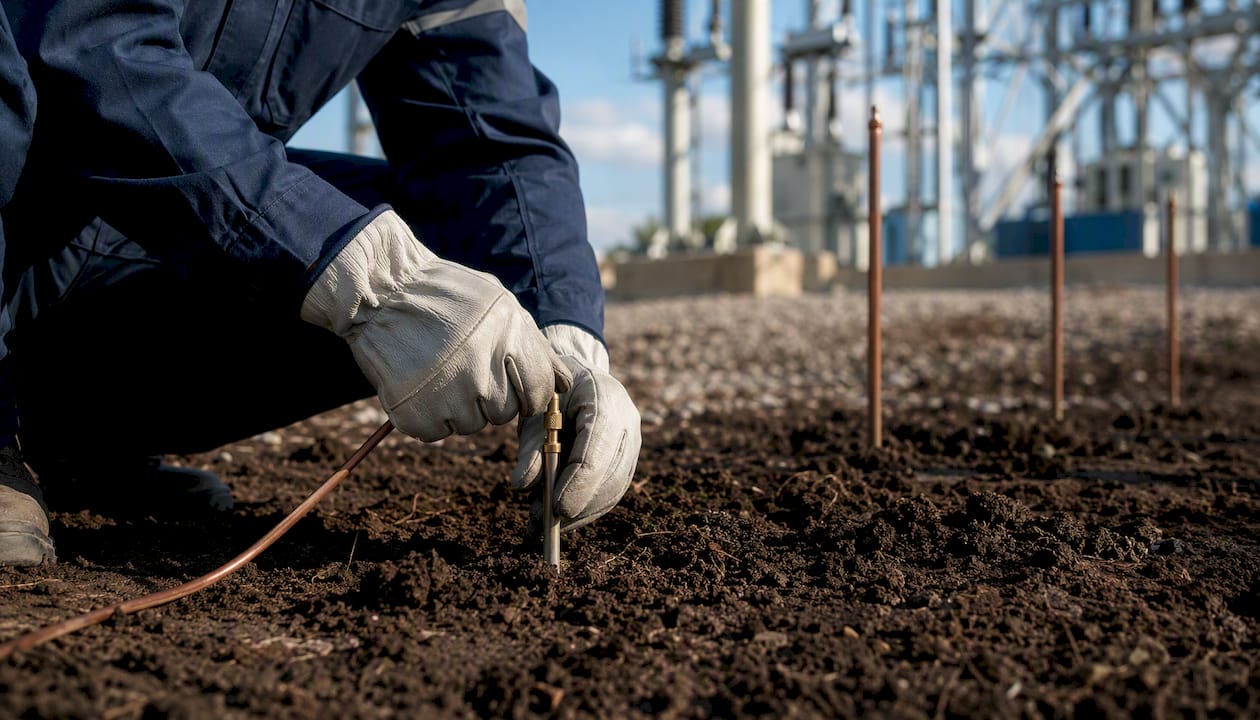
- Drive the current probe (C2) in line with the electrode, at a distance of at least five to ten times the electrode’s buried length — for a standard 1.5 m rod, a minimum of 10 m, and ideally 30–50 m in heterogeneous ground.
- Drive the potential probe (P2) between the electrode and C2. Start at roughly 62% of the C2 distance from the electrode.
- Connect the earth tester (three- or four-terminal instrument) and record the reading at the 62% position.
- Move P2 to 52% and 72% of the C2 distance and record both readings. If all three readings agree within roughly 5%, the middle value is your result. If they diverge significantly, the C2 probe is too close — extend it further and repeat.
- Log the result with date, weather conditions, and probe spacings.
At that exact fractional distance, the mutual interference between the current and potential probes theoretically cancels out, giving you the cleanest estimate of remote earth resistance. In non-homogeneous ground, plot resistance readings across multiple P2 positions and look for the flat portion of the curve — that plateau is your true value, not any single point.*
Clamp-on earth testers
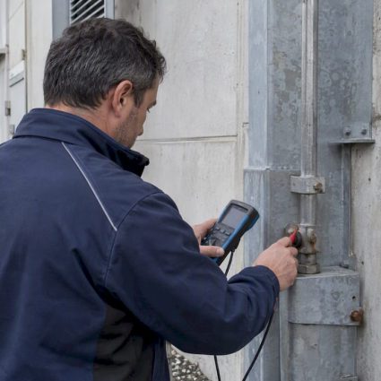
Clamp-on instruments measure earth resistance without disconnecting the electrode, by injecting a test signal through the clamp and measuring the return current through all parallel paths. They are fast and non-disruptive, which makes them useful for routine checks on multi-electrode systems. The limitation is that they cannot isolate a single electrode — if parallel paths exist (and they almost always do in a bonded installation), the reading reflects the combined network, not the individual rod. Use clamp-on results as trend indicators, not as commissioning measurements.
Wenner four-pin soil resistivity
For design work or when you need to understand why a site has high resistance, the Wenner method gives you soil resistivity in Ω·m. Four pins are driven in a straight line at equal spacing a. The outer two carry current; the inner two measure voltage. Resistivity ρ = 2π·a·R, where R is the measured resistance. Vary the spacing to profile resistivity at different depths. This is the input data for electrode system design — not a pass/fail check, but the foundation for specifying rod depth, grid dimensions, or backfill requirements.
Equipment checklist:
- Three- or four-terminal earth tester (purpose-built ground resistance instrument)
- Probe stakes (typically 300–500 mm steel spikes)
- Insulated test leads, color-coded
- Steel hammer and tape measure (30 m minimum)
- PPE: insulating gloves, safety glasses
- Test record sheet or data logger
Common errors to avoid:
- Placing C2 too close to the electrode — the most frequent cause of low, optimistic readings
- Testing immediately after heavy rain (artificially low) or during a prolonged dry spell without noting conditions
- Leaving bonding conductors connected during a three-point test, which creates parallel paths that mask the true electrode resistance
- Poor probe contact in dry, stony ground — water the probe holes slightly and re-drive if resistance at the probe itself is high
- Running test leads parallel to buried cables or pipes, which induces interference voltages
Typical target values by application
The table below reflects industry-referenced engineering targets used in France and internationally. These are practical benchmarks, not statutory limits. Regulatory requirements in France may specify functional outcomes (disconnection times, touch-voltage limits) rather than a single ohm threshold.
| Application | Typical target (Ω) | Basis / notes |
|---|---|---|
| Residential / commercial installation | ≤ 100 Ω | NF C 15-100 functional requirement; lower is better |
| General grounding (engineering target) | ≤ 5 Ω | Industry-standard engineering benchmark |
| Lightning protection system (NF EN 62305) | ≤ 10 Ω | Per-electrode target; lower preferred for high-risk structures |
| HV substation / power utility | ≤ 1 Ω | Step-and-touch voltage control; site-specific calculation required |
| Hospital / data center / sensitive facility | ≤ 1–2 Ω | Equipment sensitivity and fault-return path requirements |
| Telecom / sensitive electronics | ≤ 1 Ω | Signal reference integrity and surge protection effectiveness |

A practical note on the 25 Ω figure: some guides cite this as a code-check threshold (drawn from NEC guidance in the US context). In French practice under NF C 15-100, the relevant requirement is functional — the protective device must operate within the required disconnection time. A 25 Ω electrode may or may not satisfy that, depending on the supply impedance. For sensitive-site lightning protection, always target well below 10 Ω and verify with a full risk assessment under NF EN 62305.
How soil resistivity drives resistance — and how to fix it
Soil resistivity is the upstream variable. Get it wrong in your design assumptions and no amount of testing will make the installation perform correctly.
What drives resistivity:
- Soil type: Clay and loam typically run 20–100 Ω·m; dry sand and gravel, 500–5,000 Ω·m; limestone and granite bedrock can exceed 10,000 Ω·m.
- Moisture content: Resistivity drops sharply as moisture rises. A soil that reads 200 Ω·m in February can read 800 Ω·m in August after a dry summer.
- Salt and mineral content: Dissolved salts lower resistivity significantly, which is why coastal sites often have naturally low earth resistance.
- Temperature: Frozen ground can push resistivity to extreme values — a consideration for sites in mountainous regions of France.
Remediation options when resistance is too high:
- Deeper rods: Driving electrodes deeper helps reach more stable, lower-resistivity soil layers below surface seasonal variations. Indelec’s deep earth grounding drilling service accesses depths where surface seasonal variation has minimal effect.
- Multiple rods in parallel: Adding multiple rods in parallel reduces total resistance, with spacing recommendations to minimize mutual interference.
- Ground grids: Horizontal conductors buried at 0.5–1 m depth increase the effective contact area and are particularly effective in shallow, rocky sites where deep rods are impractical.
- Conductive backfill: Materials such as bentonite clay, graphite-based compounds, or purpose-formulated conductive concrete packed around the electrode lower contact resistance at the metal-soil interface.
- Chemical electrodes: Pre-filled hollow electrodes that leach conductive salts into the surrounding soil. Effective but require periodic replenishment and monitoring for depletion.
The trade-off with chemical backfill and salt-based treatments is corrosion. Introducing ionic material around a copper or steel electrode accelerates galvanic attack over time. Any site using chemical enhancement needs annual inspection of the electrode and connection integrity, not just a resistance reading.
Pro Tip:After any remediation, re-test under dry conditions — not immediately after installation when the backfill is still wet and artificially low. The worst-case reading, not the best-case one, is what your protection system has to perform against.
When to test and what maintenance should cover
Testing earth resistance once at commissioning and filing the result is not a maintenance program. Seasonal soil moisture and temperature shifts make earth resistance a dynamic parameter — the value measured in March after a wet winter can be two to five times lower than the same electrode in August after a dry spell. Multi-season testing is the only way to identify worst-case conditions.
Test at these moments without exception:
- At installation and commissioning (baseline)
- After any modification to the grounding system
- After severe weather events: lightning strikes, flooding, prolonged drought
- After nearby earthworks or construction that may have disturbed buried conductors
Routine cadence for operational sites:
- Quarterly spot checks using a clamp-on tester to track trends between full tests
- Annual full fall-of-potential test with probe-based instrumentation, ideally timed for the driest period of the year to capture worst-case conditions
- Soil resistivity survey every three to five years, or after significant site changes, to update design assumptions
Maintenance inspection checklist:
- Inspect all clamp connections and bonding conductors for corrosion, looseness, or mechanical damage
- Check electrode access pits for water ingress, soil settlement, or root intrusion
- Verify conductor continuity from the electrode to the main earthing terminal
- Clear vegetation from electrode access points
- Review drainage around electrode locations — pooling water distorts readings; absent water raises resistance
- Log all readings with date, conditions, and instrument serial number for trend analysis
A corroded connection can raise the measured RA even when the driven rod itself is in good condition, because the full electrode system includes the conductor and all connections back to the installation. Never assume a high reading means a bad rod until you have checked every joint in the circuit.
Standards and regulations that apply in France
France operates within the European harmonized standards framework, with AFNOR managing national transpositions. Three references cover the majority of grounding and earth resistance requirements:
- NF C 15-100: The French electrical installation standard for low-voltage buildings. Sets functional requirements for earthing systems (TT, TN, IT schemes), protective conductor sizing, and disconnection times. Does not specify a single universal ohm limit but requires that the earthing system supports the protective device’s operation within defined times.
- NF EN 62305 / IEC 62305: The lightning protection standard series. Part 3 covers physical damage to structures and covers grounding requirements for lightning protection systems, including the ≤ 10 Ω per-electrode target and the requirement for equipotential bonding. IEC/NF standards guidance from Indelec covers the French transposition context.
- IEC 61557-5: Covers testing of protective measures in low-voltage distribution systems, including earth resistance measurement methods and instrument requirements. This is the standard your test equipment should comply with.
The distinction between a technical standard and a regulatory requirement matters in practice. NF C 15-100 is referenced in French building regulations and carries legal weight for new installations and major renovations. IEC 62305 is referenced in insurance and risk-assessment frameworks. IEC 61557-5 governs instrument calibration and method validity. For real-world examples of how these standards apply, consult Indelec’s published guidance.
Always confirm the latest AFNOR transposition dates and any local utility (Enedis, RTE) earthing requirements before certifying an installation — utility interconnection rules can impose tighter targets than the base standard.
Why Indelec treats earth resistance as a time-series variable
A single commissioning test tells you the system passed on one day, in one set of soil conditions. What it cannot tell you is whether the system will perform during a summer thunderstorm after six weeks without rain, or whether a connection corroded enough over two winters to push RA above the protection threshold.
Indelec’s approach to grounding monitoring is built around trend analysis rather than point-in-time compliance. For sites under maintenance contract, the sequence runs: baseline mapping at commissioning (full fall-of-potential with soil resistivity profiling), quarterly clamp-on spot checks logged against the baseline, and an annual full probe-based test timed for the driest seasonal window.
This matters most for lightning protection systems, where the grounding electrode is the final link in the protection chain. A lightning protection system that passes its commissioning test but degrades silently over three years of corrosion and dry summers is not providing the protection the risk assessment assumed. Automated trending catches that drift. A single annual test, taken in favorable conditions, often does not.
That gives engineering teams time to schedule remediation before the system reaches a failure condition.
A field perspective on what the numbers actually mean
One pattern that shows up repeatedly on site: a system that tested at 4 Ω at commissioning reads 18 Ω three years later during a summer inspection. The instinct is to blame the rod. In most cases, the rod is fine. What changed is a combination of a dry season pushing resistivity up, a corroded clamp connection adding 6–8 Ω on its own, and a bonding conductor that had been partially disconnected during a renovation and never properly reconnected.
The fix is rarely just driving another rod. It is a systematic check of every connection in the circuit, a clamp-on reading at each joint to isolate where the resistance is sitting, and then targeted remediation — tighten or replace the corroded clamp, reconnect the bonding conductor, and only then decide whether the electrode itself needs augmentation.

The discipline that separates reliable grounding from paper compliance is treating every high reading as a diagnostic problem, not a pass/fail verdict. Plot your readings over time. Note the conditions. When the trend moves, find out why before the next lightning season.
Indelec’s grounding and earth resistance services
When measured resistance exceeds target values and site-level remediation has not resolved the problem, the next step is a professional soil resistivity survey and engineering assessment.

Indelec provides grounding surveys, deep-earth borehole drilling, conductive backfill installation, ground grid design, and seasonal monitoring contracts for industrial, commercial, and infrastructure sites across France. For lightning protection installations, Indelec’s service scope covers the full chain: risk assessment under NF EN 62305, electrode system design, installation, and periodic certification. Sites requiring ongoing compliance can arrange a monitoring contract that includes quarterly spot checks, annual full testing, and threshold-based remediation alerts.
To arrange a site survey or discuss a monitoring contract, contact Indelec through the lightning protection services page.
Indelec’s perspective on what most sites get wrong
The conventional wisdom is that earth resistance is a commissioning check. Pass it once, file the certificate, move on. That framing is wrong, and it is wrong in a specific, consequential way: it treats a dynamic physical measurement as a static administrative fact.
Soil is not a fixed medium. It dries, freezes, shifts, and corrodes the electrodes embedded in it. A grounding system that met its target on the day of installation may be operating at three times that resistance two summers later, with no visible sign of failure and no alarm to trigger an inspection. The protection system above it — the lightning rod, the surge protectors, the fault-clearing devices — is designed around an assumed earth resistance. When that assumption is violated silently, the protection chain is broken silently.
The sites that get this right are not the ones with the most expensive electrodes. They are the ones that treat earth resistance as a monitored variable, the same way they monitor temperature or pressure in a process system. Quarterly readings, logged against a baseline, with a defined threshold for action. That is not overcaution. It is the minimum that a time-varying parameter requires.
Sources
The references below are the primary sources used in this article. Consult them directly for method details, instrument requirements, and official standard text.
- Scientific Reports (seasonal monitoring of ground resistance)
- Reeve_Ground Testing R1-1 (application note)
- Don’t forget the grounding system | Fluke blog
- Earth resistance: definition, factors, and measurement methods | Electrical4u
- High earth resistance | Causes and solutions for UK | Elec-Mate