Industrial lightning protection guide for reliable facilities
TL;DR:
- Industrial lightning risks involve unplanned current paths through steel, pipes, and equipment frames.
- Site-specific risk assessments and bonding are essential for effective lightning protection and safety.
- Regular maintenance, testing, and system updates are crucial to ensure long-term protection reliability.
Lightning doesn’t follow the path you planned for it. Most facility managers assume that installing a lightning rod means the facility is protected, but in industrial environments, that assumption can lead to costly failures and serious safety incidents. Steel frames, complex piping networks, sensitive electronics, and volatile substances all interact with lightning energy in ways that generic protection approaches don’t address. This guide breaks down the real risks, evidence-based standards, and practical steps you need to build lightning protection that actually holds up under real-world conditions.
Table of Contents
- Why lightning risk in industry is different
- Core standards and proven protection strategies
- System components: Pipes, grounding, and industrial design
- Applying a reliable site evaluation and upgrade process
- What most facilities miss about lightning protection systems
- Take the next step: Proven industrial lightning solutions
- Frequently asked questions
Key Takeaways
| Point | Details |
|---|---|
| Industry vulnerabilities | Industrial facilities face unique lightning risks that require tailored, evidence-backed protection solutions. |
| Standards matter | NFPA 780 remains the baseline for industrial lightning protection, but must be applied with awareness of facility-specific challenges. |
| Critical components | Grounding, bonding, and proper pipe protection are essential for compliance and operational safety. |
| Site-specific action | Effective evaluations and upgrades rely on hands-on, facility-tailored approaches, not just checkbox compliance. |
| Continuous improvement | Regular review and adaptation are key to overcoming hidden vulnerabilities and staying resilient against lightning threats. |
Why lightning risk in industry is different
Industrial facilities aren’t just bigger buildings. They carry unique electrical, structural, and operational risks that make standard lightning protection approaches fall short in ways you may not expect.
The most important insight comes from empirical research. In one documented pharmaceutical plant study, the steel skeleton carried 80% of lightning current during a 200kA strike, while the dedicated conductors handled only 20%. That same event induced 180 amps in power cables running through the facility. That’s not a design failure in the lightning rod itself. It’s a fundamental misunderstanding of how current distributes through a steel-framed building.
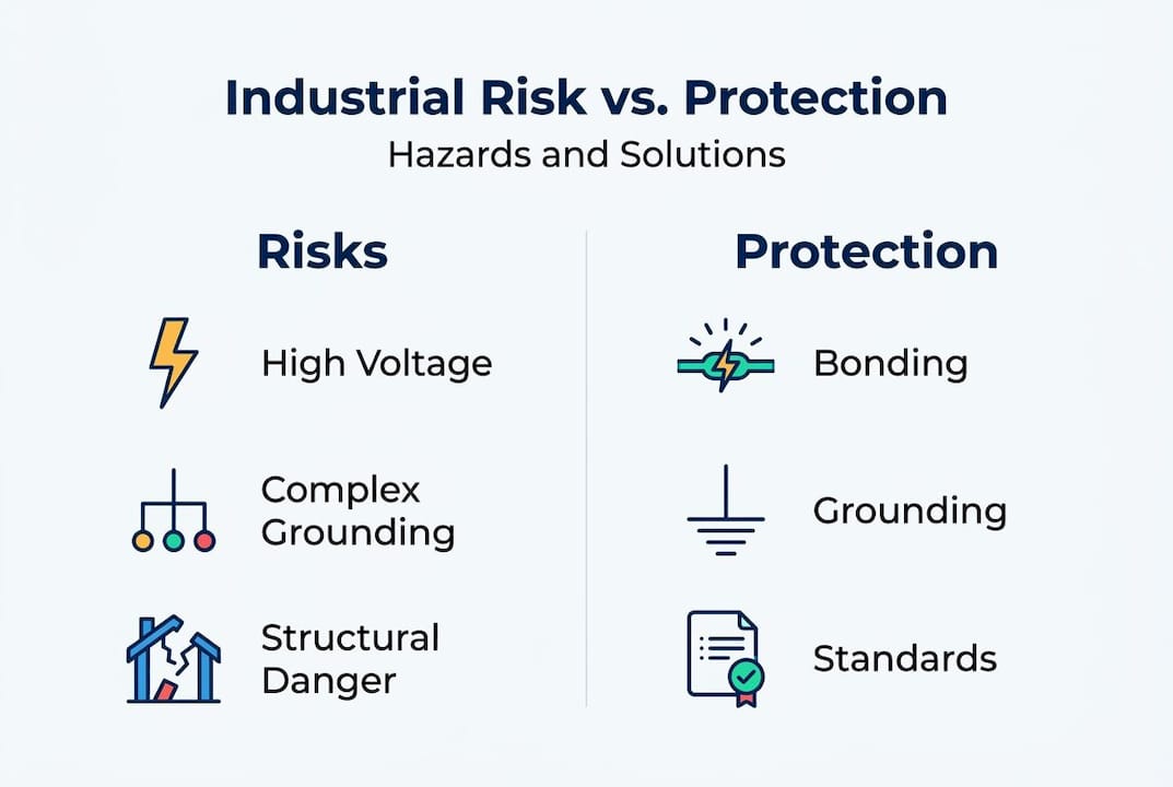
This matters because the dedicated lightning protection system (LPS) you invested in may only be handling a fraction of the actual current. The rest flows through structural steel, unintentionally connected pipework, cable trays, and equipment frames, creating potential differences that damage electronics, ignite flammable atmospheres, and put workers at risk.
Industrial facilities compound this problem through several additional factors:
- Complex layouts with multiple building sections, outdoor process equipment, and elevated structures that create varied exposure levels across a single site
- Critical equipment density, including control systems, variable speed drives, PLCs, and sensors that are highly sensitive to induced currents and transient voltages
- Volatile or flammable substances in storage tanks, pipelines, and process areas where a single ignition event from a spark at a poorly bonded joint can be catastrophic
- Regulatory and insurance scrutiny that is significantly stricter for industrial operators than for commercial or residential properties
“The assumption that a lightning rod protects the whole facility ignores how modern industrial structures actually conduct electricity. Steel, pipes, and cable trays create an unplanned conduction network running through your entire operation.”
Understanding the real lightning hazards in facilities means looking at the whole conduction network, not just the air terminals on your roof. Facilities that treat lightning protection as a checkbox exercise routinely discover gaps only after a damaging event. The industrial lightning safety guide outlines why site-specific thinking matters from the very first risk assessment.
Core standards and proven protection strategies
Once you understand why industrial risk is different, the next question is which standards and strategies actually work and which ones create a false sense of security.
NFPA 780 and the standard baseline
NFPA 780 is the primary lightning protection standard used in the United States for industrial facilities. It covers air terminal placement, conductor sizing, grounding requirements, bonding, and surge protection. For most industrial operations, NFPA 780 serves as both the legal baseline and the technical foundation for design.
The IEC 62305 series, widely used internationally, takes a risk-based approach. It calculates the probability of a lightning strike and the likely consequences based on building characteristics, occupancy, and contents. This framework is particularly useful when NFPA 780’s prescriptive approach may not capture the full complexity of a given site. For facilities operating under international regulatory frameworks, or for installations in regions where IEC standards are required, understanding both systems is essential.
Here is how the two approaches compare across key criteria:
| Criteria | NFPA 780 | IEC 62305 |
|---|---|---|
| Approach | Prescriptive rules and fixed specifications | Risk-based, site-specific calculation |
| Hazardous area guidance | Limited; criticized for complex risks | More detailed for explosive atmospheres |
| U.S. regulatory alignment | Primary standard for insurance and code | Less commonly required in the U.S. |
| Flexibility for complex sites | Lower | Higher |
| Empirical grounding | Strong for standard structures | Strong, with detailed risk quantification |
Why dissipation arrays don’t make the cut
Dissipation arrays are marketed as devices that reduce the probability of a strike by bleeding off charge from the atmosphere. They are sometimes presented as an alternative to conventional LPS. However, dissipation arrays lack peer-reviewed evidence for strike prevention, and NFPA 780 is preferred over alternatives that cannot demonstrate empirical data supporting their effectiveness.
For industrial facility managers, this matters directly. If your insurer or regulatory body requires compliance with NFPA 780, a dissipation array installation does not satisfy that requirement. Beyond compliance, the absence of peer-reviewed validation means you are accepting unquantified risk in exchange for an unproven benefit.
Pro Tip: Always ask vendors for third-party peer-reviewed validation of any technology they claim outperforms conventional LPS. If they can’t provide it, treat the claim with serious skepticism.
Protecting hazardous and explosive zones
Hazardous zones, including areas where flammable gases, vapors, or dusts may be present, require specific measures that go beyond standard LPS design. The key requirements are:
- Use an insulated LPS with a minimum separation of 3 meters from hazardous zones to prevent arc-over
- Recognize that sparking up to 2 meters from joints risks ignition in poorly bonded systems
- Supplement conventional protection with detailed hazardous area classification under ATEX or NEC Class/Division requirements
- Conduct a dedicated risk assessment for each zone, not a single facility-wide evaluation
To protect your facility effectively, your protection design must account for these zone-specific requirements explicitly. Reviewing industrial lightning standards in detail will clarify exactly where the prescriptive baseline ends and where engineering judgment must take over.
System components: Pipes, grounding, and industrial design
Understanding the standards is necessary, but the real protection comes from getting the component-level decisions right. Two areas consistently separate adequate installations from genuinely reliable ones: piping system protection and grounding electrode system performance.
When pipes protect themselves and when they don’t
Not all industrial piping needs dedicated lightning protection hardware. Under NFPA 780 Article 7.3.2.6, pipes are self-protecting if metallic, electrically continuous, sealed, and have walls at least 4.8mm thick. When those conditions are met, the pipe itself acts as a natural conductor that safely carries lightning current to the grounding system.
When any of those conditions is not met, you need to add either air terminals spaced no more than 50 feet apart along the run, or an overhead ground wire providing a 100-foot protection radius per terminal. And regardless of whether a pipe meets the self-protecting criteria, flammable pipes require flame arrestors at all vulnerable points.
Here is a practical reference for common pipe scenarios:
| Pipe type | Self-protected? | Additional requirement |
|---|---|---|
| Metallic, continuous, sealed, wall ≥4.8mm | Yes | Verify bonding continuity |
| Metallic but wall <4.8mm | No | Air terminals or overhead ground wire |
| Non-metallic or non-continuous | No | Full LPS treatment required |
| Flammable content (any type) | Partial | Flame arrestors always required |
Grounding: The benchmark that matters most
The entire LPS depends on the grounding electrode system performing reliably. The ground resistance benchmark is 10 ohms or less for effective dissipation. For sites with poor soil conductivity, or where sensitive electronics are present, you should target significantly lower values, often under 5 ohms.
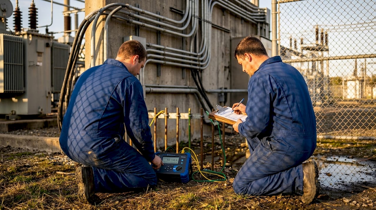
Soil resistivity testing is not optional on industrial sites. Sandy, rocky, or dry soils dramatically increase ground resistance and may require chemical ground rods, deep driven electrodes, or conductive backfill to achieve the target value.
The following factors directly affect grounding performance and must be evaluated during design:
- Soil resistivity measured in ohm-meters across seasonal variations
- Number and depth of ground electrodes and how they are interconnected
- Bonding between the LPS ground and the facility’s electrical service ground and equipment grounds
- Corrosion resistance of electrode materials, particularly in chemically aggressive soils near process areas
Pro Tip: Test ground resistance seasonally for the first two years after installation. Soil conditions change, and a system that passes its initial commissioning test can degrade significantly during dry summer months.
For facilities managing electrical infrastructure safety, bonding is the piece that ties grounding performance to the rest of the facility. A well-designed sensitive site design example demonstrates how to integrate these elements into a coherent, measurable system. Understanding protection zones for industrial facilities adds another layer of structured thinking to site design decisions.
Applying a reliable site evaluation and upgrade process
Knowing what good protection looks like is only half the job. The other half is building a reliable process to assess where you stand today and prioritize what to fix.
Step-by-step site evaluation
- Start with a site survey, mapping all structures, process equipment, outdoor storage, pipelines, and cable runs. Note building materials, roof heights, and adjacency to hazardous zones.
- Conduct a risk assessment using NFPA 780 or IEC 62305 methodology. Generic templates fall short here because industrial layouts vary enormously. A custom calculation, accounting for structure type, equipment value, occupancy, and local keraunic level (a measure of how many thunderstorm days per year occur at your location), will give you a defensible result.
- Inspect and test the existing LPS, including air terminals, down conductors, bonding connections, grounding electrodes, and surge protective devices (SPDs). Measure ground resistance and compare to the 10-ohm benchmark.
- Map steel structure paths through the facility. As the steel skeleton carries majority current in many industrial buildings, verify that all structural steel is properly bonded to the grounding system. Unbonded sections create unpredictable current paths and potential ignition points.
- Identify protection zone gaps, paying special attention to transitions between buildings, outdoor process areas, and any zones housing sensitive electronics or flammable materials.
- Prioritize upgrades based on risk level, consequence severity, and compliance requirements. Fix grounding deficiencies and bonding gaps first, as these affect the performance of everything else.
Common gaps found during site evaluations
- Air terminals missing from low-slope roof sections or equipment platforms
- Down conductors that are corroded, damaged, or disconnected at test joints
- Bonding absent between structural steel and the LPS grounding conductor
- SPDs installed without coordination with upstream protection, reducing their effectiveness
- No surge protection on instrumentation, data, or communication lines entering or leaving the building
The facility lightning safety workflow provides a structured sequence for moving from initial assessment through commissioning and ongoing maintenance, which is essential for facilities managing multiple structures or phased upgrade programs.
Pro Tip: Document every test result, inspection date, and corrective action with photographs. This documentation protects you during regulatory audits and insurance claims, and it builds the maintenance record that supports ongoing system confidence.
What most facilities miss about lightning protection systems
Here is the perspective that most standard guides won’t tell you directly: lightning protection compliance and lightning protection reliability are not the same thing.
A facility can pass every checklist item in NFPA 780 and still suffer a damaging event, because real-world lightning behavior interacts with industrial structures in ways that prescriptive rules don’t fully anticipate. The pharmaceutical plant study referenced earlier is not an anomaly. It is a representative example of what happens when engineers design for the dedicated LPS without accounting for the unplanned conduction network running through the building’s structural steel.
The facilities that truly reduce risk treat bonding as the core of their protection strategy, not an afterthought. Every piece of structural steel, every major metallic pipe run, every cable tray, and every equipment frame needs to be integrated into a single, low-impedance equipotential system. When everything is bonded together and tied to a well-performing ground, the potential differences that cause damage and ignition are dramatically reduced, even when current flows through unplanned paths.
The second missed element is the living system approach. Lightning protection degrades. Connections corrode, test joints are accidentally bridged during maintenance, additional equipment is installed without updating bonding, and soil conditions shift. A protection system that was excellent at commissioning can become marginal within five to seven years without structured maintenance and periodic re-testing.
The uncomfortable truth is that checkbox compliance, where you install the system, get the certification, and move on, creates a liability without creating genuine safety. Facilities that review real-world protection examples and apply those lessons to their own sites consistently outperform those that treat lightning protection as a one-time installation exercise.
The facilities getting this right are the ones where protection is treated as an ongoing engineering discipline rather than a project that ends at commissioning. That shift in mindset is more valuable than any single component upgrade.
Take the next step: Proven industrial lightning solutions
Applying everything in this guide is a substantial undertaking, and the decisions you make at the design and assessment stage have long-term consequences for safety, compliance, and operational continuity.
Indelec has been engineering lightning protection solutions for industrial facilities since 1955, with installations across manufacturing, pharmaceuticals, energy, and infrastructure sectors worldwide. Our team combines standards expertise with hands-on site experience to deliver protection systems that perform under real conditions, not just on paper. If your facility needs a risk assessment, a system audit, or a full protection design, our industrial lightning protection solutions and industry lightning standards resources are built to match your operational complexity. Start with our industrial site lightning guide for a practical framework, or contact our team directly for a site-specific consultation.
Frequently asked questions
What is the recommended ground resistance for industrial lightning protection?
A ground resistance of 10 ohms or less is the standard benchmark, with lower values required for sites with poor soil conductivity or sensitive electronic equipment.
When do industrial pipes need dedicated lightning protection?
Pipes require air terminals or overhead ground wires unless they are metallic, electrically continuous, sealed, and have walls at least 4.8mm thick per NFPA 780. Flammable pipes require flame arrestors regardless of whether they meet the self-protecting criteria.
Is there evidence that dissipation arrays prevent lightning strikes?
No. Dissipation arrays lack peer-reviewed evidence for strike prevention, and NFPA 780-based conventional systems remain the only approach supported by empirical data and recognized by compliance bodies.
Can steel structures replace dedicated lightning conductors?
Steel structures carry the majority of lightning energy unintentionally in many industrial buildings, but they must never be treated as a substitute for a properly designed and bonded dedicated LPS. They must be bonded into the overall system, not relied upon independently.
What special measures are needed in hazardous or explosive industrial zones?
Hazardous zones require insulated LPS with at least 3 meters of separation from the zone boundary, since sparking up to 2 meters from joints can cause ignition. All flammable piping in those areas must also include flame arrestors regardless of pipe wall thickness.
Recommended
- Building contractor lightning guide: Safe solutions for industrial sites
- Building lightning safety: protect your facility effectively
- Step-by-step guide to infrastructure lightning protection
- Lightning risk assessment guide: protect your facility
- Wat is overspanningsbeveiliging? essentiële gids 2026 – Holland Electric Duurzaam