Step-by-step power grid surge control for safer facilities

TL;DR:
- A single uncontrolled voltage spike can destroy critical equipment, cause costly downtime, and disrupt production lines. Implementing a layered surge protection strategy, starting from the main service entrance and including point-of-use devices, effectively reduces transient voltages to safe levels. Regular testing, proper grounding, and ongoing maintenance are essential to sustain reliable protection and prevent expensive failures.
A single uncontrolled voltage spike can destroy a variable frequency drive (VFD), halt an entire production line, and leave your team scrambling to source replacement parts for weeks. That scenario is far more common than most facility managers expect. VFD failures costing $25k plus another $100,000 in downtime have been traced directly to inadequate surge coordination. Effective surge control is not about plugging in a single protective device and calling it done — it requires a deliberate, layered strategy that accounts for every entry point, every vulnerable asset, and every maintenance cycle across your facility.
Table of Contents
- Assessing your facility’s surge risk
- What you’ll need: Tools, devices, and preparation
- Step-by-step surge control: Layered implementation
- Testing, verification, and ongoing maintenance
- Why most facilities under-protect: Lessons from the field
- Advanced solutions for your surge control needs
- Frequently asked questions
Key Takeaways
| Point | Details |
|---|---|
| Layered protection is vital | Using a multi-stage SPD approach is essential for real-world surge control and equipment safety. |
| Proper grounding saves equipment | Low-resistance and short-path grounding is critical for surge device effectiveness. |
| Verification prevents downtime | Regular testing and maintenance help avoid costly failures and keep your facility protected. |
| Expert support accelerates results | Consulting with specialists gives you tailored protection strategies and greater peace of mind. |
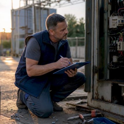
Assessing your facility’s surge risk
Before purchasing a single device or pulling a single wire, you need a clear, honest picture of where your facility stands today. Skipping this step is exactly how facilities end up with mismatched protection that leaves critical equipment exposed.
Start by mapping every potential surge entry point. The three primary paths for destructive transients are the main service entrance, subpanels feeding sensitive zones, and data or control cabling running alongside power conductors. Each of these pathways can carry a surge from an external lightning strike, a utility switching event, or even an internal motor start into your most vulnerable equipment.
Next, catalog what you already have. Walk every electrical room and equipment area and document:
- Existing SPDs (surge protective devices) at the main service entrance and subpanels, noting their voltage protection rating (VPR) and whether status indicators show them as functional
- Sensitive equipment such as PLCs (programmable logic controllers), VFDs, CNC machines, medical imaging systems, and server infrastructure
- Grounding infrastructure, including the condition and routing of ground conductors
- Any history of unexplained equipment failures, nuisance trips, or data corruption events
That last point is crucial. A well-kept incident log is one of the most underused diagnostic tools in facility management. When you correlate equipment failures with weather events or utility records, patterns emerge that reveal exactly where your protection gaps are.
A layered approach is essential because upstream SPDs at the service entrance will reduce a 10 kV spike to around 2.5 kV, but that residual voltage is still lethal to sensitive electronics. A single-stage installation simply cannot protect the full chain of equipment. For a structured starting framework, the SPD facility guide and surge protection explained resources walk through facility-specific planning in detail.
You also need to assess your geographic and operational risk. Facilities in high-keraunic (high lightning frequency) regions face a very different threat profile than a building in a low-strike area. Switching surges from large motor loads, capacitor bank switching by your utility, and nearby industrial equipment can generate transients just as damaging as a direct lightning event. For guidance on critical power protection standards relevant to sensitive equipment zones, that resource provides useful benchmarks.
Pro Tip: Request ten years of utility switching records and overlay them with your equipment failure log. In roughly 60% of cases, you will find a direct correlation that tells you exactly which subpanel needs priority attention.
What you’ll need: Tools, devices, and preparation
With a clear risk assessment, it’s time to gather the right tools and prep the site for robust surge control. Showing up to a panel room with the wrong SPD rating or inadequate grounding hardware means wasted time and repeat visits.
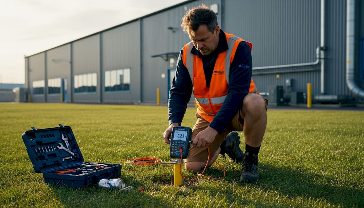
Grounding requirements are non-negotiable. The grounding specification for an effective surge protection system calls for less than 5 ohms resistance, conductor runs under 3 meters with no splices, minimum 6 AWG copper, and a single-point ground topology. Deviating from any one of these criteria significantly degrades your system’s ability to divert surge energy away from equipment.
Here is a practical checklist of what you’ll need on site:
| Item | Specification | Purpose |
|---|---|---|
| Type 1 SPD | 25 kA or higher, compliant with IEC 61643 | Main service entrance protection |
| Type 2 SPD | 20 kA minimum, coordinated VPR | Subpanel and distribution board |
| Type 3 SPD | 5 kA, low clamping voltage | Point-of-use, sensitive equipment |
| Ground resistance tester | Digital, ≤0.01 ohm resolution | Verification of grounding integrity |
| Clamp meter | True RMS, 1000V CAT III | Electrical measurement during commissioning |
| 6 AWG copper conductors | Stranded, listed for grounding | Ground bus connections |
| Ferrule connectors | Rated for conductor size | Termination integrity in panels |
| PPE (personal protective equipment) | Arc flash rated for facility NFPA 70E level | Safety during installation |
| Cable labels | UV-resistant, machine-printed | Documentation and traceability |
You’ll also want a voltage event recorder deployed at key panels for at least 72 hours before installation begins. This gives you a real baseline: how many transient events occur per day, what their magnitude is, and whether your planned SPD ratings are correctly sized.
Pro Tip: Buy SPDs with remote monitoring outputs. The marginal cost is small, and the ability to detect a sacrificed device before the next storm arrives is worth far more than the price difference.
For additional context on safeguarding industrial facilities with coordinated protection strategies, that resource covers selection criteria for different facility types and load categories.
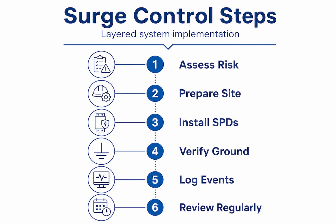
Step-by-step surge control: Layered implementation
With materials on hand, follow this sequence for complete, coordinated surge defense. Order matters here. Installing downstream devices before the upstream stage is properly commissioned creates a false sense of security.
Commission the service entrance SPD first. Install a Type 1 SPD at the main service entrance panel, as close to the meter as local code allows. Short lead lengths are critical. Leads add 1 kV/m of inductive voltage drop at a surge rise rate of 10 kA/μs, meaning a 0.5-meter lead difference is not trivial — it directly affects how much voltage reaches your equipment. Bond the SPD ground lead to the grounding electrode system with the shortest possible path.
Test service entrance grounding before proceeding. Confirm ground resistance below 5 ohms with your ground resistance tester. If you’re over this threshold, add ground rods, improve bonding, or consult a licensed engineer before continuing. This is a go/no-go checkpoint.
Install subpanel Type 2 SPDs. For each subpanel feeding sensitive equipment zones, install a coordinated Type 2 SPD. Verify the voltage protection rating (VPR) of the Type 2 device is compatible with the downstream Type 3 devices you plan to use. Mismatched VPR levels are one of the most common errors seen in field installations and they undermine the entire layered strategy.
Deploy Type 3 SPDs at point-of-use locations. Install these directly at or within 1 meter of sensitive equipment: PLCs, VFDs, HMI panels, and server racks. These devices handle the residual transients that slip past the upstream stages.
Perform coordination checks. Verify that each stage’s let-through voltage is lower than the immunity level of the next downstream device. Document VPR values at each stage and compare them against equipment manufacturer specifications.
Inspect and label all connections. Every connection must be torqued to specification, labeled with installation date and device rating, and photographed for your records. This documentation is essential for insurance claims and future maintenance.
A panel SPD reduces 10 kV to 2.5 kV under typical surge conditions — an impressive reduction, but still far above the 1.5 kV immunity threshold of many PLCs and VFDs. That gap is exactly why layered protection is essential rather than optional.
Single-stage vs. layered protection — the numbers tell the story clearly. A single Type 2 SPD at the subpanel may leave 2.5 kV reaching your VFD. A coordinated three-stage system can reduce that to under 800 V, well within the equipment’s rated immunity. That difference is the gap between years of reliable service and a $25,000 drive replacement.
| Scenario | Surge voltage at equipment | Outcome |
|---|---|---|
| No SPD installed | Up to 10 kV+ | Immediate equipment failure |
| Single-stage Type 2 at subpanel | ~2.5 kV residual | Likely failure of sensitive electronics |
| Coordinated three-stage system | Under 800 V | Equipment within immunity threshold |
Common wiring errors to avoid: reverse polarity on SPD terminals, excessively long ground leads, sharing a ground conductor between multiple SPDs, and installing Type 3 devices without a functioning Type 2 upstream. Each of these mistakes erases the performance your investment should deliver.
For more guidance on building out a comprehensive electrical protection strategy, the facility safety guide covers upgrade sequencing in detail, and adaptation strategies addresses how evolving weather patterns are raising the bar for surge protection standards.
Pro Tip: When selecting clamp voltage levels for Type 3 devices, always reference the equipment manufacturer’s impulse withstand voltage (IWV), not just the nominal operating voltage. Many engineers miss this distinction and oversize their Type 3 devices, leaving a protection gap at the last line of defense.
Testing, verification, and ongoing maintenance
Installing surge controls is only effective if you verify and maintain them — here’s how to ensure lasting protection beyond commissioning day.
Verification steps immediately after installation:
- Measure and document grounding resistance at each SPD connection point. All readings must be below 5 ohms.
- Inspect every device status indicator. Most modern SPDs use a green/red window or LED to confirm the varistor (the internal protective element) is intact.
- Use a power quality analyzer to confirm baseline voltage at sensitive equipment panels. Any readings above nominal by more than 10% warrant investigation before normal operations resume.
- Conduct a visual inspection of all lead lengths, labeling, and termination torque values. Use a calibrated torque wrench and log each connection.
Ongoing maintenance schedule:
- Monthly: Visual inspection of all SPD status windows. Replace any device that shows a fault indicator, regardless of whether a surge event was recorded.
- Quarterly: Review the event log from any connected monitoring systems. Cross-reference with weather records to ensure your system is performing as expected during storm activity.
- Annually: Full ground resistance testing at all grounding points, plus thermal imaging of all panel connections to detect high-resistance joints before they fail.
The power quality strategies resource outlines a structured maintenance framework specifically built for industrial facility power systems.
Statistic callout: Facilities that implement properly coordinated, three-stage surge protection and maintain documented maintenance logs report a measurable reduction in unplanned downtime related to transient events. The benchmarks consistently show that lead inductive effects alone — at 1 kV/m at 10 kA/μs rise rate — can account for hundreds of volts of additional stress that a poorly installed system fails to account for.
Pro Tip: Set a calendar reminder every six months to pull your event logs and review them with your electrical contractor. The pattern of small, frequent transients often predicts a catastrophic failure event before it happens.
Why most facilities under-protect: Lessons from the field
After years of evaluating surge protection systems at industrial and commercial facilities globally, a clear pattern emerges. The majority of facilities that experience serious surge-related losses were not entirely unprotected — they were under-protected in specific, predictable ways.
The most common failure mode is the cost-driven single-stage install. The logic sounds reasonable on the surface: “We have an SPD at the main panel, so we’re covered.” But this ignores what happens downstream. A single-stage installation consistently fails to protect sensitive electronics because the residual let-through voltage after even a good Type 2 SPD still exceeds the immunity ratings of PLCs, VFDs, and instrumentation systems.
The second overlooked detail is lead length. We have walked into facilities where a well-specified SPD was installed with a 1-meter ground lead when a 20-centimeter path was achievable. That extra 80 centimeters, given a fast surge front, added nearly a kilovolt of inductive drop that bypassed the SPD entirely. No one noticed until the next lightning season brought a rash of unexplained controller failures.
Event logging is the third gap. Facilities that keep detailed logs of transient events, correlated with storm activity and equipment health records, catch degrading SPDs before they fail silently. An SPD that has absorbed one very large surge or dozens of smaller ones may look functional on the outside while its internal varistor is essentially worn out. Without logs, you have no way to know.
The blueprint that top-performing facilities use looks like this: a coordinated three-stage SPD system, ground resistance tested to below 3 ohms for extra margin, event monitoring with quarterly log reviews, and annual thermal imaging of all panel connections. They also build surge resilience into procurement standards, requiring manufacturers to provide impulse withstand voltage specifications before purchasing any new control equipment.
For a deeper look at how electrical infrastructure planning supports long-term safety, infrastructure safety insights covers the strategic layer that sits above individual device selection.
The uncomfortable truth is that surge protection is not a one-time capital expense — it’s an ongoing operational discipline. Facilities that treat it as a checkbox item consistently pay for that decision in repair costs and unplanned downtime.
Advanced solutions for your surge control needs
If you’re ready to close the gaps in your facility’s surge defense with proven technology and expert guidance, the right starting point is a tailored assessment that accounts for your specific load profile, geographic risk, and equipment sensitivity.

Indelec brings more than seven decades of electrical protection expertise to industrial and commercial facilities worldwide. From engineered grounding systems to advanced lightning air terminals like the Prevectron3, our solutions are designed to work together as a coordinated system rather than isolated products. Our technical teams can evaluate your current protection level and recommend a phased upgrade path that prioritizes your highest-risk areas first. Explore our full range of lightning protection system applications to see how a purpose-built protection strategy translates into measurable uptime and safety gains for facilities like yours.
Frequently asked questions
What is the ideal grounding resistance for surge protection?
Less than 5 ohms is the recommended maximum for surge protection system grounding, though targeting 3 ohms or below provides additional safety margin for high-value installations.
How do I know if my facility needs layered surge protection?
If you operate sensitive equipment such as VFDs, PLCs, or server infrastructure, a single SPD is not adequate because upstream devices leave residual surges that still exceed the immunity threshold of most electronics.
What are typical maintenance steps after surge device installation?
Check grounding resistance measurements at all connection points monthly, inspect SPD status indicators after every storm event, and maintain a logged record of device readings and any detected transient activity.
How much downtime or damage can poor surge control cause?
Inadequate surge coordination has been directly linked to failures costing $25k or more in replacement equipment, plus over $100,000 in associated production downtime per incident — a compelling case for investing in a properly layered system.
Can I retrofit surge protection or do I need to redesign my grid?
In most cases, you can retrofit a coordinated multi-stage SPD system at your existing service entrance, subpanels, and equipment locations without a full electrical redesign, provided your grounding infrastructure meets specification.