Make IEC 62305 Work on French ATEX Sites With Isolated LPS

ATEX-classified areas need coordinated protection: an isolated external lightning protection system (LPS) with ATEX-certified components, surge protective devices (SPDs) rated for Ex zones, and grounding you can verify. Skip any one layer and you have an ignition path, not a protection system. French sites carrying explosion risk also need an Analysis of Lightning Risk (ARF) and a Document Technique de Protection contre la Foudre (DTPF) on file. INDELEC designs, installs, and certifies exactly this combination.
TL;DR:
- An isolated external lightning protection system with ATEX-certified components and verified grounding is essential to prevent ignition paths in explosive zones.
- Conductors must be routed outside the zone boundary using high-voltage insulation, with air terminations sized accurately using the rolling sphere method.
- Surge protective devices inside the zone require ATEX or IECEx certification and must be staged at LPZ boundaries to reduce energy transfer to sensitive equipment.
- Grounding systems should be actively monitored with interlocked connections, especially in critical operations like tanker loading, to ensure continuous electrical safety.
- Proper documentation, including lightning risk assessments and installation verification records, is mandatory for audit compliance in high-risk ATEX environments.
Table of Contents
- Why Lightning Threatens ATEX Zones and Which Standards Govern the Design
- Mapping IEC 62305 to an ATEX Site: What Parts 2 Through 4 Actually Require
- Isolated LPS and HVI Conductors: Keeping the Strike Path Outside the Zone
- Surge Protection and the LPZ Model for Explosive Atmospheres
- Grounding and Equipotential Bonding: When Passive Isn’t Enough
- Installation, Acceptance, and Keeping Your Paperwork Audit-Ready
- What Twenty Years of Field Surveys Taught Us About ATEX Projects
- Get an ARF, DTPF, or Turnkey ATEX Lightning Protection Design From INDELEC
- Sources
Why Lightning Threatens ATEX Zones and Which Standards Govern the Design
A direct strike is not the only threat inside a classified zone. Induced overvoltage traveling through cabling, pipework, or structural steel can spark across a gap and ignite a flammable mixture just as reliably as a direct hit, and it does so without ever touching the tank or vessel itself. That is the mechanism most engineers underestimate: the ignition source can arrive through a signal cable three buildings away from where the lightning actually struck.
Zone classification (0/1/2 for gas and vapor, 20/21/22 for dust) determines how tight the design margins need to be, since it defines where an explosive atmosphere is expected to exist and for how long. Before specifying anything, pull these documents:
- IEC 62305-2, -3, -4: risk assessment, structural LPS design, and internal/electronic system protection
- IEC/EN 60079-14: electrical installation design for explosive atmospheres
- IEC 62561 series: component testing for LPS parts, including conductors and connectors
- ARF, DTPF, and the French arrêté of January 15, 2008: the regulatory backbone for lightning risk analysis and documentation in France
Mapping IEC 62305 to an ATEX Site: What Parts 2 Through 4 Actually Require
IEC 62305-2 calls for a formal risk assessment whenever a structure’s use, contents, or surroundings could turn a lightning event into a life-safety or environmental incident, which describes almost every ATEX-classified facility by default. That assessment has to account for the probability of a strike, the consequences of ignition, and the value or criticality of what is inside, not just the structure’s footprint.
Most ATEX applications justify Lightning Protection Level (LPL) I or II rather than the lower levels acceptable for ordinary commercial buildings, given the severity of a worst-case outcome. Parts 3 and 4 translate that risk level into hardware:
- External LPS geometry sized using the rolling sphere method against the actual zoning drawing, not a generic building outline
- SPD coordination across every service entering the structure, staged to match the LPZ boundaries
- Annex guidance that explicitly steers designers toward isolated systems wherever explosive atmospheres are present, rather than conventional structure-mounted air terminations
Skipping the formal risk assessment and defaulting to a standard commercial LPS is the single most common design shortcut auditors flag on ATEX sites.
Isolated LPS and HVI Conductors: Keeping the Strike Path Outside the Zone
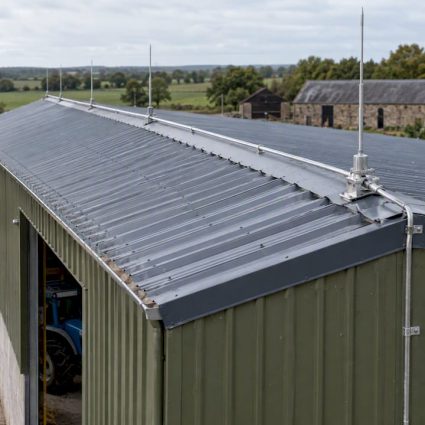
An isolated external LPS keeps the interception point, the down conductor, and the earthing infeed physically outside the classified zone, which means there is nothing inside the zone to spark or arc during a strike. Industry practice, including guidance published through IChemE, favors this approach specifically for tanks, silos, and process structures where the contents themselves are the hazard.
High-voltage-insulated (HVI) conductors carry the strike current through a heavily insulated core so the cable can run close to steel structure or piping without flashing over, which is what makes isolated designs practical on congested industrial sites. Design work typically follows this sequence:
- Overlay the ATEX zoning drawing with the rolling sphere method to place air terminations well beyond the zone perimeter
- Size separation distances between the down conductor and any conductive structure per IEC 62305-3
- Route HVI conductors with sealing ends terminated outside the zone boundary, never inside it
- Split strike current across twin-conductor mast assemblies to reduce the current each path must carry
- Specify ATEX-rated fixings throughout and eliminate mechanical joints anywhere within the classified zone
Pro Tip:Order the ATEX zoning drawing before you start the rolling-sphere layout. Reworking air termination positions after installation because the electrical contractor moved a zone boundary is the single most expensive design error on these projects.
Surge Protection and the LPZ Model for Explosive Atmospheres
Standard SPDs are not an option inside an Ex zone. Ordinary spark gaps and disconnect terminals can generate the exact arc you are trying to prevent, so every device touching the protected structure needs ATEX or IECEx certification.
Manufacturers now supply purpose-built hardware for this problem: Ex-rated spark-gap modules, certified equipotential busbars, and arrester elements such as isCon® components let a lightning conductor connect safely at the zone boundary without arcing risk. Low-voltage arresters rated specifically for ATEX zone service cover equipment sitting inside or adjacent to the classified area.
A few placement rules matter more than product selection:
- Connect the first potential equalization point at the zone boundary, never deeper inside it
- Stage SPDs to match LPZ transitions so energy is progressively reduced before reaching sensitive equipment
- Schedule inspection access for every SPD in an Ex area before installation, since retrofitting a maintenance path later usually means shutting down production
Undersized separation between the SPD’s protective level and the equipments withstand voltage is the most frequent finding when these installations get audited after the fact.
Grounding and Equipotential Bonding: When Passive Isn’t Enough
Passive grounding, meaning fixed clamps and continuous bonding conductors, works for structures and fixed equipment where connections are inspected regularly. Industry guidance generally targets a contact resistance around 10 ohms or better at bonding points, verified on a set schedule rather than assumed.
Passive systems fail silently, though. A corroded clamp or a disconnected bond looks fine until someone tests it, and loading or unloading operations depend on a human remembering to connect the bonding cable every single time. Active monitored systems close that gap: Earth-Rite® PLUS and comparable products carry SIL ratings and interlock directly with process controls, refusing to start a pump or a fill sequence until grounding continuity is confirmed. Standards such as IEC/TS 60079-32-1 recommend exactly this kind of monitored loop for critical static-discharge operations.
- Verify contact resistance at every bonding point on a documented interval
- Specify monitored, interlocked grounding for tanker loading, drumming, and any operation where operator discipline is the only safeguard
- Record equipotential bonding continuity for every structural connection, not just the ones an inspector is likely to check
Pro Tip:If your loading bay handles more than a handful of vehicles per shift, a monitored system pays for itself the first time a driver forgets to clip on the bonding cable.
Installation, Acceptance, and Keeping Your Paperwork Audit-Ready
French practice requires an ARF for high-risk establishments, and that analysis has to identify the consequences of a strike, not just its probability. The resulting DTPF then documents exactly what was installed: conductor routes, SPD locations, grounding resistance values, and the verification records tied to each.
Recommended verification follows two tracks. Visual inspections happen annually and after any lightning event in the vicinity; full electrical testing, including continuity and resistance measurements, runs on a longer interval set by the risk study itself.
- Confirm ARF findings match what was actually installed, not what was originally specified
- Check for air terminations or metallic fixings left inside the zone boundary, a documented and recurring non-compliance on audited sites
- Verify no mechanical joints exist on conductors running through the classified area
- Test every bonding point against the target resistance and log the reading, not just a pass/fail note
- Confirm SPD serviceability access has not been blocked by later equipment installations
What Twenty Years of Field Surveys Taught Us About ATEX Projects
Most ATEX lightning protection failures trace back to sequencing, not ignorance. A contractor installs conduit before the zoning drawing is finalized, or an SPD gets specified before anyone confirms which LPZ boundary it actually sits on. INDELEC’s R&D group builds designs backward from the zoning drawing for exactly this reason: risk study first, then isolated LPS layout, then SPD coordination, then installation, then verification against the original assessment.
Before a site survey, INDELEC typically requests the ATEX zoning drawings, a site plan showing existing structures and services, and a list of critical equipment that cannot tolerate downtime. Projects that arrive with these three items move to proposal noticeably faster than those that don’t.
— INDELEC
Get an ARF, DTPF, or Turnkey ATEX Lightning Protection Design From INDELEC
INDELEC is the direct route to a compliant, documented lightning protection system for ATEX zones, not a generic contractor bolting standard hardware onto a hazardous site. Where a general electrical firm might install conventional SPDs and call it finished, INDELEC’s scope covers the full sequence: ARF, isolated LPS design with HVI conductors, ATEX-certified SPD and earthing supply, installation, and the verification testing that produces your DTPF.

Before reaching out, gather your ATEX zoning drawings, a current site plan, and a list of equipment that cannot tolerate unplanned downtime. That’s the same starting point INDELEC’s engineers request for every survey, and it lets the first conversation focus on your actual risk profile instead of paperwork. Review the lightning protection system application options for classified zones, or reach out through INDELEC’s services page to schedule a site survey and get a proposal scoped to your facility.
Sources
- Lightning protection in hazardous areas — IChemE paper
- Surge protection in potentially explosive areas of industry | OBO