Lightning Protection Zone (LPZ): Engineer’s 2026 Guide
TL;DR:
- A lightning protection zone is an area where electromagnetic shielding, grounding, and surge protectors work together to prevent lightning damage. Proper LPZ classification guides the placement and selection of surge protective devices to ensure internal electronics are protected from transients. Coordinated protection systems reduce the risk of equipment failure caused by lightning strikes or induced surges within facilities.
A lightning protection zone (LPZ) is a spatially defined area within or around a facility where electromagnetic shielding, grounding, and surge protective devices work together to limit lightning-induced damage. The LPZ concept, formalized in IEC 62305, divides any structure into hierarchical zones that progressively reduce the threat from direct lightning strikes and induced electromagnetic surges. Engineers and safety officers who understand LPZ classification can design coordinated protection systems that defend both the building structure and the sensitive electronics inside it. Without this zoned approach, even a correctly installed external lightning rod leaves internal equipment exposed to destructive transient surges.
What is a lightning protection zone (LPZ) and why does it matter?
A lightning protection zone is defined by IEC 62305-4 as a region where the lightning electromagnetic environment is controlled to a specified level. The standard divides the space around and inside a facility into numbered zones, each with a distinct threat profile. Moving from the outermost zone inward, each boundary reduces the electromagnetic impulse that equipment must withstand.
The core purpose of LPZ classification is coordination. External lightning protection systems (LPS) handle the direct strike. Internal systems handle the induced surges that travel through power lines, data cables, and metallic structures. Neither system works fully without the other. Integrating both systems is the defining principle of IEC 62305-4.
The five core LPS components per IEC 62305 are air terminals, down conductors, grounding electrodes, bonding connections, and surge protective devices (SPDs). Each component plays a role at a specific zone boundary. Omitting any one of them creates a gap in protection that a transient surge will find.
What are the different types of lightning protection zones?
LPZ classification defines four primary zone categories, each with a specific electromagnetic threat level.
- LPZ 0A is the unprotected outdoor area directly exposed to lightning strikes and the full, unattenuated electromagnetic field of a lightning event. Equipment in this zone faces the highest risk. No shielding exists between it and a direct strike.
- LPZ 0B is still outdoors but sits within the protection angle of an air terminal or shielding structure. Direct strikes are prevented, but the full electromagnetic field from nearby strikes still reaches this zone. Partial lightning currents can still flow through conductors here.
- LPZ 1 is the first interior zone. The building envelope, reinforced concrete, or a dedicated metal shield attenuates the electromagnetic field. SPDs at the LPZ 0A/1 boundary intercept the high-energy surge currents before they enter the building. Induced surges are reduced but not eliminated.
- LPZ 2 and beyond are nested interior zones with additional shielding layers and SPDs at each boundary. Sensitive electronics such as programmable logic controllers, medical devices, and communication servers belong in LPZ 2 or higher. Each additional zone further reduces the residual surge energy.
The mechanism behind this graduated reduction is threefold. First, physical shielding attenuates the electromagnetic field. Second, equipotential bonding eliminates voltage differences between metallic structures inside each zone. Third, SPDs at zone boundaries clamp the surge voltage to a safe level before it reaches the next zone.
Pro Tip:Map your facility’s zones on a floor plan before selecting any SPD. The physical location of each device relative to zone boundaries determines its required impulse current rating. Getting the map wrong leads to mismatched devices.

The structural design of LPZs requires closed, fully grounded shields and equipotential bonding within each zone. This reduces differential surges and electromagnetic interference that would otherwise damage sensitive electronics even when no direct strike occurs.
How does LPZ classification drive SPD selection and coordination?
Surge protective device selection is directly governed by the zone boundary where each device is installed. IEC 62305-4 specifies that SPDs at LPZ 0A/1 boundaries must handle impulse currents of 25–100 kA. SPDs at LPZ 1/2 boundaries target finer protection with currents of 5–20 kA and voltage protection levels up to 1.5 kV.
The three SPD types map directly to zone boundaries:
- Type 1 SPDs install at the LPZ 0A/1 boundary, typically at the main electrical panel or service entrance. They carry the highest impulse current rating (Iimp) and absorb the bulk of the lightning partial current. These devices use spark gap or combined spark gap and varistor technology.
- Type 2 SPDs install at the LPZ 1/2 boundary, typically at sub-distribution boards. They handle the residual surge energy that passes through the Type 1 device. Their maximum discharge current (Imax) rating is lower, and their voltage protection level (Up) is tighter.
- Type 3 SPDs install close to sensitive terminal equipment within LPZ 2 or higher. They provide the final clamp on residual transients and have the lowest energy ratings. They must never be installed without an upstream Type 1 or Type 2 device.
The table below summarizes the key electrical parameters for each SPD type at its corresponding zone boundary.
| SPD Type | Zone Boundary | Impulse Current (Iimp / Imax) | Voltage Protection Level (Up) |
|---|---|---|---|
| Type 1 | LPZ 0A / LPZ 1 | 25–100 kA (Iimp) | ≤ 2.5 kV |
| Type 2 | LPZ 1 / LPZ 2 | 5–20 kA (Imax) | ≤ 1.5 kV |
| Type 3 | LPZ 2 and beyond | < 5 kA (Imax) | ≤ 1.0 kV |
Improper SPD coordination creates transient blind spots that destroy sensitive equipment even when SPDs are physically present. The most common error is installing a Type 2 device at the service entrance without a Type 1 upstream. The Type 2 device saturates and fails, passing the full surge to downstream equipment.
Pro Tip:Always verify the energy coordination between cascaded SPDs. The upstream device must clamp the voltage before the downstream device activates. If the voltage protection levels are too close together, the downstream device may conduct before the upstream device, reversing the intended cascade.
What practical steps should engineers follow to implement LPZ-based protection?
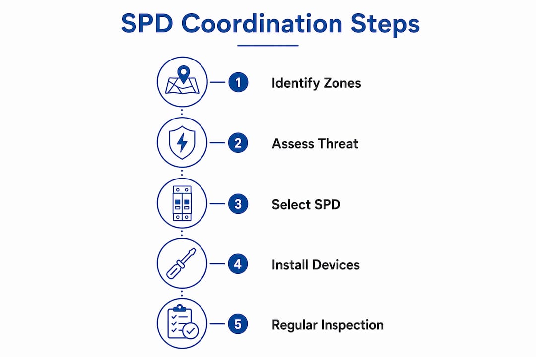
A risk assessment is the mandatory first step. It identifies the facility’s exposure to direct strikes and induced electromagnetic fields, and it produces the zone map that drives every subsequent decision.
- Step 1: Conduct a lightning risk assessment. Use IEC 62305-2 methodology to calculate the annual probability of a damaging lightning event. The result determines the required protection level (LPL I through IV) and defines which zones the facility needs.
- Step 2: Design the external LPS. Select and position air terminals, down conductors, and grounding electrodes according to the required LPL. Indelec’s Prevectron3 air terminal is one example of a device engineered to meet these placement requirements. The grounding system must achieve the lowest practical earth resistance to dissipate strike current efficiently.
- Step 3: Define internal zone boundaries. Identify the physical boundaries of LPZ 1, LPZ 2, and any additional nested zones. Reinforced concrete walls, metal cable trays, and dedicated shielded enclosures all serve as zone boundaries. Document each boundary on the facility plan.
- Step 4: Install SPDs at every zone boundary. Select Type 1, 2, and 3 devices based on the electrical parameters required at each boundary. Install bonding conductors to connect all metallic structures to the equipotential bonding bar at each zone entry point.
- Step 5: Verify coordination and commission the system. Test grounding resistance, inspect bonding connections, and verify SPD installation against the design drawings. Schedule periodic inspections, because SPDs degrade after absorbing surges and must be replaced before they fail silently.
Pro Tip:After any significant lightning event near the facility, inspect all Type 1 and Type 2 SPDs for degradation. Many devices have a visual indicator, but a degraded device can still pass continuity tests while offering no surge protection.
Safeguarding industrial facilities through LPZ implementation requires treating the external and internal systems as one integrated design, not two separate projects. Facilities that commission them separately almost always end up with coordination gaps at the LPZ 0A/1 boundary.
How does LPZ fit within broader lightning safety standards?
The LPZ concept is the internal protection framework within the IEC 62305 series. IEC 62305-1 defines general principles. IEC 62305-2 covers risk assessment. IEC 62305-3 addresses external LPS design. IEC 62305-4 is the LPZ standard, specifying internal protection through coordinated SPDs and shielding.
NFPA 780, the American standard for lightning protection installation, governs building-level external protection in the United States. It does not replace IEC 62305-4 for internal electronic protection. Facilities operating under NFPA 780 still require an IEC 62305-4 compliant internal protection strategy to protect electronics.
Several common misconceptions persist among facility teams:
- An external lightning rod alone protects all equipment inside the building. It does not. The external LPS protects the structure from fire and collapse. Internal electronics require coordinated SPDs within the LPZ framework.
- A single SPD at the main panel is sufficient. It is not. One device at the LPZ 0A/1 boundary leaves LPZ 1/2 boundaries unprotected, and residual surges reach sensitive equipment.
- Higher-rated SPDs are always better. They are not. Oversized SPDs at inner zone boundaries may fail to clamp low-energy transients that fall below their activation threshold.
“External lightning protection and internal surge protection are not alternatives. They are sequential layers of the same defense. Removing either one does not halve the risk. It eliminates the protection entirely for the threat that layer was designed to stop.”
The 2026 revision cycle for IEC 62305 reinforces the requirement for documented zone maps and SPD coordination records as part of facility compliance audits. Facilities without these records face compliance gaps regardless of whether physical devices are installed.
Key takeaways
The LPZ concept is the only framework that coordinates external lightning protection and internal surge protection into a single, verifiable defense system for electrical infrastructure.
| Point | Details |
|---|---|
| LPZ definition | IEC 62305-4 defines zones by electromagnetic threat level, from fully exposed LPZ 0A to shielded interior zones. |
| SPD selection by zone | Type 1 SPDs handle 25–100 kA at LPZ 0A/1 boundaries; Type 2 and 3 devices protect inner zones with tighter voltage limits. |
| Coordination is mandatory | Cascaded SPDs must be energy-coordinated; a gap at any boundary creates a blind spot that destroys equipment. |
| External LPS is not enough | An external lightning rod protects the structure but leaves internal electronics unprotected without internal LPZ measures. |
| Risk assessment comes first | IEC 62305-2 risk assessment determines the required protection level and drives every zoning and device decision. |
Indelec’s perspective on coordinated LPZ implementation
The most persistent failure mode we see in the field is not a missing air terminal or a broken ground rod. It is a Type 1 SPD installed at the main panel with nothing at the LPZ 1/2 boundary. The external system looks complete on paper. The internal system has a gap that no visual inspection reveals until a lightning event destroys a server room or a control panel.
Multi-zone deployment is genuinely difficult. Zone boundaries in older facilities are rarely clean. A reinforced concrete wall that should form the LPZ 1 boundary has cable penetrations, conduit runs, and HVAC ducts that bypass the shielding entirely. Each penetration is a path for a surge to skip the zone boundary and arrive at sensitive equipment with full energy. Closing those paths requires coordination between electrical, mechanical, and structural teams, and that coordination rarely happens without a single engineer owning the LPZ design from start to finish.
Maintenance is the other gap. SPDs degrade silently. A device that absorbed a 50 kA surge two years ago may show a green indicator light today and offer no protection tomorrow. Facilities that treat SPD installation as a one-time event rather than a maintained system are operating on borrowed time. Annual inspection and post-event inspection protocols are not optional for facilities with critical electronics.
The stakeholders who need to understand this most are not always engineers. Facility managers who approve maintenance budgets and safety officers who sign off on compliance documentation need to understand that an SPD replacement program is not a discretionary expense. It is the difference between a functioning protection system and a system that looks correct on a drawing but fails the moment it is needed.
— Indelec
Indelec’s lightning protection solutions for LPZ-based systems
Indelec has designed and installed lightning protection systems that integrate external LPS components with internal SPD coordination across LPZ boundaries since 1955. The approach covers air terminals, grounding, bonding, and SPD selection as a single engineered system rather than separate procurement decisions.

For engineers and safety officers working on new builds or retrofitting existing facilities, Indelec provides technical consulting, zone mapping, and full system design aligned with IEC 62305-4 and NFPA 780. The team also supports compliance with current lightning standards and can assist with the documentation required for 2026 audit cycles. Contact Indelec directly to discuss your facility’s protection requirements and get a coordinated LPZ design that covers every zone boundary.
FAQ
What is the LPZ definition in IEC 62305?
A lightning protection zone (LPZ) is a region defined by IEC 62305-4 where the lightning electromagnetic environment is controlled to a specified level through shielding, bonding, and SPDs. Zones range from fully exposed LPZ 0A to progressively shielded interior zones.
How many lightning protection zones are there?
IEC 62305-4 defines a minimum of four zones: LPZ 0A, LPZ 0B, LPZ 1, and LPZ 2. Facilities with highly sensitive equipment can add further nested zones (LPZ 3 and beyond) to reduce residual surge energy to the lowest possible level.
Does an external lightning rod protect internal electronics?
An external lightning rod protects the building structure from fire and physical damage, but it does not protect internal electronics. Internal protection requires coordinated SPDs installed at each LPZ boundary per IEC 62305-4.
What SPD type belongs at the main electrical panel?
A Type 1 SPD installs at the main panel, which corresponds to the LPZ 0A/1 boundary. It must carry an impulse current (Iimp) rating of 25–100 kA to handle partial lightning currents entering the building at that point.
How often should SPDs be inspected in an LPZ system?
SPDs require annual inspection and an additional check after any significant lightning event near the facility. Degraded devices can retain a green status indicator while offering no surge protection, so visual checks alone are not sufficient.