Clamp-On Ground Testing: Method, Limits and Readings
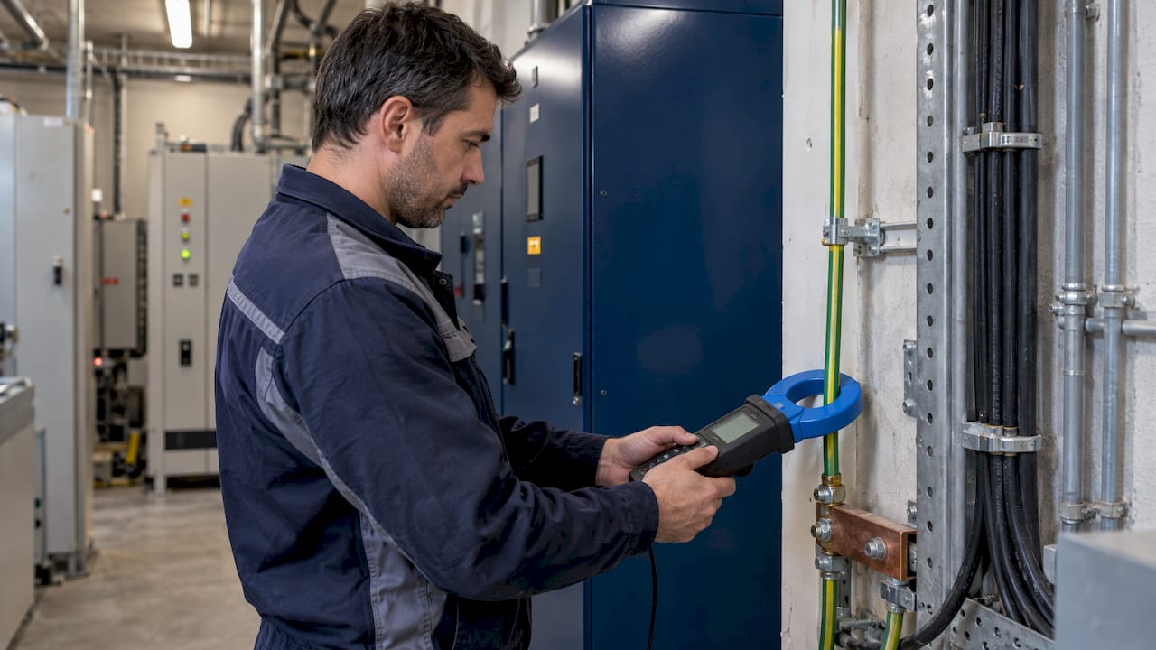
Clamp-on ground testing measures the resistance of a complete earth loop without disconnecting the electrode and without driving test stakes. It is fast and well suited to periodic checks on multi-grounded sites, but it only gives a valid figure when a closed return path exists. For a new electrode, an isolated lightning protection earth or a commissioning report, an independent method is required. Indelec’s lightning protection verification and maintenance service puts the right method on the right earth termination.
TL;DR
- A clamp induces a known voltage into the ground loop, measures the resulting current and returns the loop resistance (R = V/I). No stakes and no disconnection are needed.
- It works only where several parallel earth paths close the circuit. On an isolated electrode, the tester has nothing to measure.
- The reading is the whole loop: the electrode plus bonds, conductors and the other paths. A high figure can point to a poor connection, not only to poor soil contact.
- Resistance (near mains frequency) is not impedance (lightning-shaped current). For lightning protection systems, the difference matters.
- Use clamp-on for periodic verification and trend tracking. Use fall of potential to commission or to prove a new earth.
Table of Contents
- What clamp-on (stakeless) testing actually measures
- When clamp-on testing is the right tool
- When the reading is unsuitable or misleading
- How to take a clamp-on reading, step by step
- Ground resistance or ground impedance: why it matters for lightning protection
- What value counts as acceptable in France
- Checking a clamp-on result against other methods
- Mistakes that cost the most
- Promo: verification and maintenance by the lightning protection specialist
- Perspective
- FAQ
- Sources
What clamp-on (stakeless) testing actually measures
A clamp-on ground tester has two coils in one jaw. One coil induces a known voltage into the conductor you clamp around. The other measures the current that flows back through the loop. The instrument divides voltage by current, following Ohm’s law, and displays the result.
The number is the resistance of the whole loop in series: the electrode you clamped, the return path through the other grounded elements, and every conductor and joint in between. In practice the return path usually has a much lower resistance than the electrode under test, so the reading is dominated by the electrode and its connection. That is why the method is popular on sites with many grounding points, such as industrial plants, substations, telecom masts or buildings with a meshed earthing network.
Two consequences follow:
- You need a closed loop. The method works without disconnecting the electrode, provided there are multiple parallel earth paths to complete the circuit.
- You must know the topology. Because the instrument reads loop resistance, not the resistance of one electrode in isolation, the person testing has to understand how the site is bonded.
The same logic explains why the method is called stakeless: where the traditional approach needs auxiliary probes placed at set distances in the soil, the clamp uses the existing network as its return circuit.
When clamp-on testing is the right tool
Clamp-on testing fits a specific situation: an existing, multi-grounded installation where you want to check that connections and electrodes have not degraded.
Typical uses for facility and maintenance teams:
- Periodic checks on earthing of production buildings, tanks, tower bases and process areas where disconnecting the earth for a test would interrupt operations.
- Dense urban or paved sites where there is no soil to drive auxiliary stakes into.
- Trend tracking, where you measure the same points each year and watch for drift.
- Finding bad bonds. Clamp-on testing captures both the electrode resistance and the integrity of bonding connections, so a high reading may indicate a poor bond rather than a poor electrode.
It is also the quicker method. One technician can test dozens of points in the time a probe-based test takes on a handful, which is why it suits maintenance rounds across large facilities.
When the reading is unsuitable or misleading
The method has clear limits, and most wrong results come from ignoring them.
Isolated electrodes. Clamp-on testers cannot measure single or independent groundings that lack a return path. A lone earth rod at a lightning rod down conductor, not bonded to anything else, gives no meaningful reading. Where an earth termination is deliberately separate, an independent method is the right one.
New electrodes. A clamp reading is generally not sufficient alone to commission a new electrode. The clamp reads a loop, so it cannot give the independent value that an acceptance report needs.
Noise current. Stray current in the loop can make the display unstable or prevent a measurement. Many instruments also measure ground current first. On one widely used model family, if ground current exceeds 5 A, the resistance measurement is not possible. Check your own instrument’s range in its manual.
Dirty or misaligned jaws. Dirt trapped in the clamp head can cause false low readings. Clean the jaw surfaces and make sure they close completely before every series of measurements.

A parallel path you did not know about. If an unrecorded bond, a metallic pipe or a cable screen provides a second route, the reading looks better than the electrode really is. This is the most dangerous error because the figure looks reassuring. It is the reason an up-to-date earthing drawing matters before any test.
How to take a clamp-on reading, step by step
- Define the loop. From the site drawings, identify which electrode you are testing and which parallel paths close the circuit. If the drawings are missing or out of date, resolve that first. Verification by a specialist, such as Indelec’s verification and maintenance service, starts from the lightning protection installation and its records.
- Inspect the tester. Check the jaws are clean and close completely, and that the battery and any calibration check are in order.
- Clamp around the conductor. Place the jaws around the ground conductor or rod, above the point where it joins the grid, so the full electrode current passes through the jaw.
- Read the ground current first. If the instrument reports current above its limit, stop. Do not force a resistance measurement.
- Take the resistance reading. Wait for the figure to stabilize. An unstable display usually means noise current or poor jaw contact.
- Record the context. Note the point identifier, date, instrument, soil and weather conditions, and which parallel paths existed. A bare number cannot be compared next year.
- Compare against the previous value and the design value. A sudden rise on one point suggests a corroded or loose bond. A uniform change across many points suggests seasonal soil effects.
Where the measurement involves work on an electrical installation, the safety rules of the installation apply. In France, INRS points to consignation under NF C 18-510 as the way to make sure voltage is removed and stays removed, and the work must be carried out by personnel with the appropriate electrical authorization.
Ground resistance or ground impedance: why it matters for lightning protection
A clamp-on tester injects a small current at a frequency close to the mains. What it returns is a resistance. Lightning behaves very differently: it is a fast impulse with high-frequency content, and the earth termination answers it with an impedance, not a simple resistance.
The distinction is set out in the lightning standards. Ground resistance is measured with current near mains frequency, while ground impedance is measured with current shaped to correspond to lightning. The EN 62305 series distinguishes between earth resistance and earth impedance for lightning protection systems.
| Ground resistance | Ground impedance | |
|---|---|---|
| Test current | Near mains frequency | Shaped to simulate lightning |
| Typical tool | Fall of potential, clamp-on | Impulse measurement |
| What it tells you | Low-frequency contact with soil, bond quality | How the earth behaves during a strike |
| Main use | Periodic verification, commissioning | Studies of sensitive or large earth networks |
For most facilities, a low resistance remains the working indicator of a sound earth termination, and the geometry of the electrodes is what keeps impedance low at lightning frequencies. A clamp-on figure is therefore evidence about the condition of the loop. It does not on its own describe how the system responds to a direct strike on a large or highly sensitive site. For such sites, the design and verification approach is worth discussing at study stage, as in Indelec’s highly sensitive site design example.
What value counts as acceptable in France
There is no single number that applies to every installation. The acceptable value depends on the type of earth termination and on what it serves:
- Lightning protection systems follow the lightning risk analysis (ARF) and the technical study (ET) produced for the site, under the EN 62305 series. The study states the earth termination requirement for that site.
- Low-voltage electrical installations follow the NF C 15-100 series. The 2024 edition applies to new installations and extensions from September 2025, but it is not yet incorporated into regulations: the 2002 version and its amendments remain mandatory. The series provides the fundamental rules for design, implementation and verification of low-voltage installations.
- Protection of people relies on earthing of exposed conductive parts combined with automatic disconnection of the supply, so the acceptable earth value is tied to the protective devices installed.
If your site is classified as an ICPE (installation classée), your lightning study and the associated prefectoral requirements set the verification frequency and the records you must keep. Ask who wrote the study and keep it with the measurement records. For the standards framework, see Indelec’s overview of lightning standards.
Checking a clamp-on result against other methods
Treat clamp-on as one tool. Fall-of-potential results can be checked by varying the probe positions and confirming the curve flattens. Clamp-on results cannot be proofed this way, so a doubtful figure needs a second method, not a second clamp.
A workable rule for facility teams:
- Commissioning of a new earth termination: fall of potential, with the earth isolated from the rest of the network. Indelec’s guide to the fall of potential test covers method, steps and pitfalls.
- Annual or periodic verification of a bonded network: clamp-on at each accessible point, with fall of potential on a sample or where a reading is out of trend.
- Any isolated lightning earth: independent measurement only.
- After a strike, modification or extension: a full verification, with the earthing drawing updated.
Some instruments support several methods, including 3-pole and 4-pole measurements, which lets one team cover both cases with a single device. Routine upkeep of the earthing network itself is covered in the guide to maintaining grounding systems.
Mistakes that cost the most
- Reporting a loop figure as an electrode figure. The report should say what was measured.
- Testing without drawings. Unknown bonds produce reassuring but wrong readings.
- Comparing readings from different conditions. Frozen, dry and saturated soil give different values. Record the weather.
- Skipping the lightning-specific view. A good mains-frequency value does not replace the lightning risk analysis and technical study.
- Filing numbers without actions. A rising trend needs a decision: inspect the bond, repair, re-measure.
Promo: verification and maintenance by the lightning protection specialist
Indelec has worked in lightning protection since 1955. For facility owners and maintenance managers, we cover lightning risk analysis and technical study, installation, verification and maintenance, as well as deep earth drilling. That means the person who checks your earth termination knows how the lightning protection system was designed and where its earth connections run.

If you want your earthing and lightning protection verified against the study for your site, start from our lightning protection services, or browse our earthing products.
Perspective
A clamp-on figure is only as good as the knowledge of the network behind it. Over decades of lightning protection work, the pattern we hold to is simple: design the earth termination for the site, document it, and verify it with the method that matches how it was built.
That is why we treat measurement as part of the lightning protection system, not as a separate task. The risk analysis defines the requirement, the installation delivers it, and verification proves it stays that way. A clamp-on reading is a fast, useful check inside that loop, and a periodic fall-of-potential test closes the proof.
For owners and facility managers, our advice is to keep the earthing drawing, the technical study and every measurement together, so each new reading has a baseline. Our teams support that chain from study to maintenance, including deep earth grounding where soil resistivity is the constraint.
INDELEC
FAQ
Can I use a clamp-on tester on a single earth rod?
No. A lone rod with no return path gives no loop to measure, so the instrument cannot return a meaningful value. Use an independent method such as fall of potential for isolated electrodes, including most dedicated lightning earths.
Is clamp-on testing accurate enough for a commissioning report?
Generally not on its own. It measures a loop, and its results cannot be cross-checked by moving probes. For a new electrode, use fall of potential, and keep clamp-on for later periodic checks against that baseline.
What is the difference between ground resistance and ground impedance?
Resistance is measured with current close to mains frequency. Impedance is measured with current shaped like lightning, and EN 62305 distinguishes the two for lightning protection systems. Resistance is the usual working indicator, impedance describes the response to a strike.
Why is my clamp reading unstable?
The usual causes are noise current in the loop, dirty or incompletely closed jaws, or a loop that is not really closed. Clean the jaws, check the ground current first and review the earthing drawing. If it stays unstable, switch to an independent method.
Sources
- Measuring ground loop resistance without stakes
- Clamp-on ground testing guide
- How do clamp-on earth testers make measurements?
- Soil resistivity and ground resistance workbook
- Standards guide
- INRS: Risques électriques, prévention
- AFNOR: NF C 15-100 series