French Installers: 5G Antenna Lightning Protection, GDT Coax & SPDs
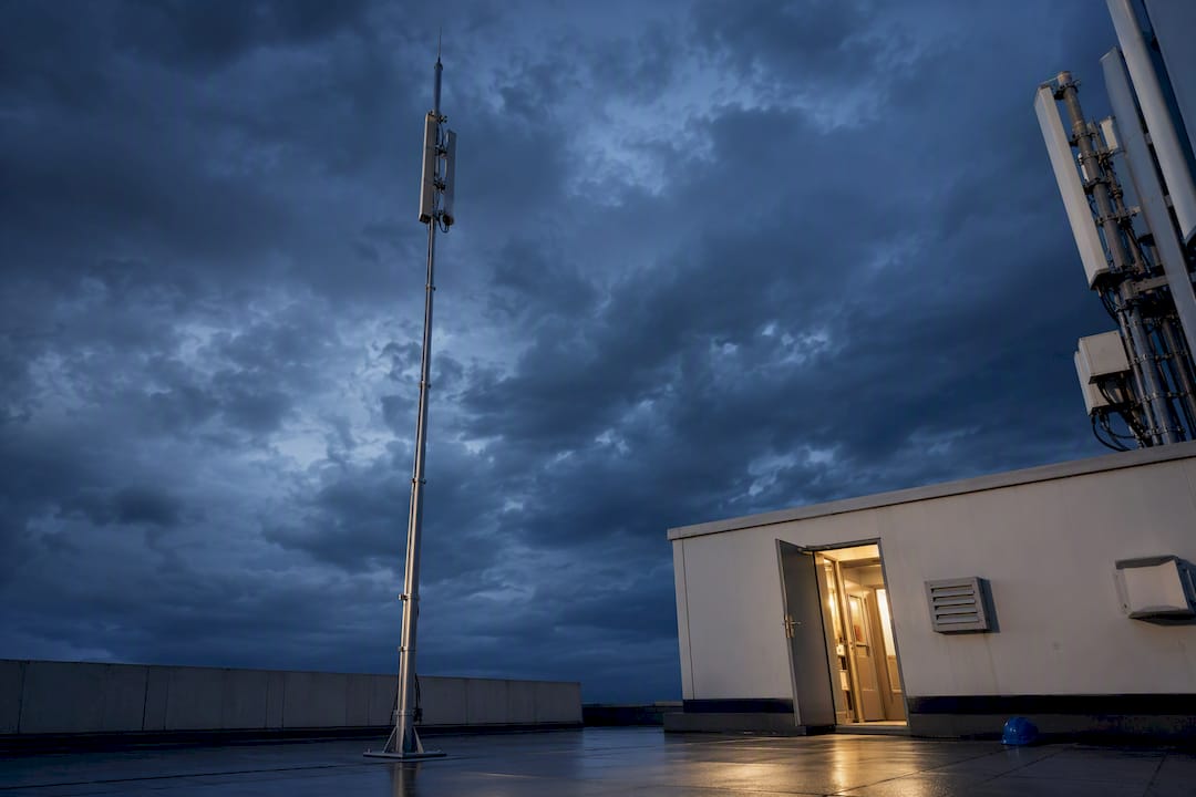
A 5G antenna site needs layered lightning protection, not a single device. That means an external LPS where risk assessment calls for one, coordinated Type 1/Type 2 SPDs on power and data lines, a gas discharge tube arrestor on every coax feeder, and a bonded earthing network tying it all together. Both direct strikes and induced surges from nearby lightning can destroy radio equipment, so no single arrestor at the antenna port is enough on its own.
TL;DR:
- Proper lightning protection for 5G sites requires both external air-termination systems and coordinated SPDs on power and data lines, not just a single device.
- Coax surge protectors should be placed as close to the antenna feed as possible and verified with fail-safe indicators to prevent false confidence in damaged units.
- Bonding the entire metallic infrastructure into a single, low-resistance earthing network is essential to prevent dangerous potential differences during a lightning event.
- Ensuring short lead lengths for all SPD-to-earth connections and routing backhaul over fiber helps maintain device performance and reduces surge entry points.
Table of Contents
- Layered Protection Architecture: External LPS and Internal SPDs Working Together
- Choosing Coax SPDs Without Degrading RF Performance
- How Do You Protect Power and Data Lines Feeding the Radio Unit?
- Grounding and Bonding: The Part Installers Underrate
- What Standards Govern 5G Antenna Lightning Protection?
- Installation, Commissioning, and Maintenance Checklist
- What Makes INDELEC’s Technical Approach Different
- What Happens When 5G Sites Skip Proper Lightning Protection
- Budgeting for 5G Antenna Lightning Protection Systems
- Why Most 5G Lightning Protection Advice Stops Too Early
- Get a Site-Specific Lightning Protection Survey
- Sources
- FAQ
Layered Protection Architecture: External LPS and Internal SPDs Working Together
An external lightning protection system (LPS) captures a direct strike and routes the current to ground through air-termination rods and down-conductors, keeping that energy off the structure’s active equipment. Internal SPDs handle something different: the surges induced on cables even when the tower itself isn’t hit directly. Protection for 5G infrastructure has to cover the whole installation, from the air-termination system down to every incoming power and data conductor, because a gap anywhere in that chain becomes the path of least resistance for a surge.
Skip the coordination step and you get one of three failure modes: direct strike current finding an unintended path through cabling, induced voltage riding in on a “protected” line that has no SPD, or a transferred potential jumping between two structures bonded at different reference points.
A quick site mapping exercise before design work starts:
- Mast and antenna: external LPS if the risk assessment calls for one, plus a coax GDT arrestor at the feed point.
- Cable runs (feeder, power, Ethernet): SPDs at every entry point where a cable transitions from outdoor to indoor.
- Shelter or equipment cabinet: secondary SPDs at the equipment rack, bonded to the same earthing reference as the mast.
- Grounding network: a single, low-impedance system tying mast, shelter, cable trays, and building steel together.
Choosing Coax SPDs Without Degrading RF Performance
The coax feeder is where most 5G antenna protection strategies fall down, mainly because installers worry about insertion loss more than surge capacity. Both concerns are legitimate. Industry-standard coaxial SPDs for antenna feeders typically deliver 5 kA to 10 kA of discharge capacity at an 8/20 microsecond waveform, using gas discharge tube technology, while holding insertion loss under 0.5 dB. That combination is achievable with the right component. It is not automatic.
Placement matters as much as the spec sheet. Put the arrestor as close to the antenna feed point as physically practical, then add a second unit at the building or shelter entry. Bond the feeder shield to the mast and to the site’s main earthing point using a proper earthing kit rather than an improvised clamp.
Key specification points for procurement:
- Match connector type to the feed line: N-type and SMA dominate 5G small-cell and macro installs; F-type shows up on older or hybrid installations.
- Verify impedance matching (typically 50 ohms for cellular, not 75 ohms) before ordering.
- Confirm an IP-rated enclosure for outdoor mounting, since a compromised seal defeats the surge protection over time.
- Commercial antenna surge protectors with up to 10 kA discharge capacity are readily available as a reference point for what “adequate” looks like on a datasheet.
Pro Tip:Order coax arrestors with a visible fail-safe indicator whenever the option exists. A dead SPD that looks fine from the ground is worse than no SPD at all, because it gives false confidence during an inspection.
How Do You Protect Power and Data Lines Feeding the Radio Unit?
PoE-fed radios and shelter electronics need their own coordinated SPD strategy, separate from the antenna feeder. A coordinated approach uses Type 1 SPDs at the service entrance and Type 2 SPDs at the equipment level, with short lead lengths between the SPD, the earthing point, and the protected equipment. Long or looped leads add inductance that lets residual voltage spike past what the connected gear can withstand.
- Install a Type 1 SPD at the main power service entrance to handle direct-strike current on the utility feed.
- Install a Type 2 SPD at the distribution panel or rack level to catch residual and induced surges the Type 1 device doesn’t fully absorb.
- Add a common-mode SPD on the Ethernet or PoE run, placed right at the injector and again where the cable enters the rack.
- Keep every SPD-to-earth lead as short and straight as possible. Every extra foot of lead length degrades the device’s clamping performance.
- Where feasible, route backhaul over fiber rather than copper, which removes a conductive lightning entry path entirely.
Practical gateway guidance backs this up directly: even the electrical field from a nearby strike, not a direct hit, can destroy connected equipment if Ethernet and PoE lines aren’t protected.
Grounding and Bonding: The Part Installers Underrate
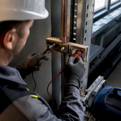
A lightning protection system is only as good as its earthing network. The objective is a low-resistance path to ground and controlled surface voltage gradients, so no two points on the site sit at meaningfully different potentials during a strike. Every metallic element on site (feeders, cable trays, tower legs, shelter frame) needs to bond into one common earthing network, not a collection of separate local grounds.

Use proper earthing kits rather than field-improvised connections, and apply protective coatings on outdoor bonding points to slow corrosion, which is the single biggest reason earthing systems degrade over time according to ARA35’s technical guidance on antenna earthing.
Practical steps that hold up over years, not just at commissioning:
- Bond the feeder shield, mast structure, and shelter frame to a single reference earth point.
- Use exothermic welds or corrosion-resistant mechanical connectors at every bonding joint.
- Schedule periodic retightening of mechanical bonds, since thermal cycling loosens them faster than most maintenance plans assume.
- Recheck coating integrity on outdoor connectors annually in coastal or high-humidity zones.
Pro Tip:Document your earth resistance reading at commissioning and treat it as a baseline, not a one-time compliance check. A resistance value that creeps upward year over year usually means corrosion or a loosened bond, long before it causes a visible failure.
Detailed bonding practices for towers and shelters, including separation distances from active antenna equipment, are laid out in Indelec’s highly sensitive site protection design guidance.
What Standards Govern 5G Antenna Lightning Protection?
Two reference frameworks matter for RBS lightning protection design: ITU-T’s K-series recommendations and the IEC 62305 family. ITU-T K.56 explicitly links lightning-protection design to IEC 62305 risk assessment, and it gives concrete procedures for feeder bonding, earthing kits, and SPD coordination on radio base stations specifically, which is more useful for a 5G site than the general IEC standard alone.
The rolling-sphere method is how you decide whether a given mast or shelter roof needs an air-termination system at all, and where to place it if so. You roll an imaginary sphere, sized to the target lightning protection level (LPL), across the structure; anything the sphere touches needs protection, anything it can’t reach because of an existing air terminal’s shadow doesn’t. It’s a geometric method, not a guess, and it’s how ITU general guidance frames the separation distance needed between an air-termination path and active antenna equipment to avoid dangerous coupling.
SPD coordination follows its own rules under this same guidance:
- Primary (Type 1) devices carry the highest energy and switch first.
- Secondary (Type 2) devices at equipment level have a lower turn-on voltage and clean up what the primary device lets through.
- The two must be coordinated so residual voltage always stays below the connected equipment’s withstand rating, not just below the SPD’s own rated voltage.
Installation, Commissioning, and Maintenance Checklist
Get the routing decisions right before cables go into conduit. A pre-install survey should map every cable path to avoid creating unintentional conductive loops between the mast and the shelter, since a loop is exactly the geometry that couples induced surges into equipment that’s otherwise “protected.”
- Pre-install: survey cable routes, confirm earthing kit locations, and verify SPD placement won’t create long lead lengths.
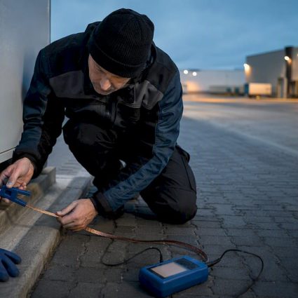
- Commissioning: test every SPD’s fail-safe indicator, measure earth resistance at each ground rod, and confirm continuity across every bonding joint.
- Documentation: record baseline earth resistance and SPD serial numbers for the maintenance file.
- Ongoing maintenance: inspect SPD status indicators, check for corrosion at bonding points, and verify protective coatings annually.
Recommended practice ties replacement triggers to specific events: swap an SPD once its fail-safe indicator trips, and inspect the full site after any documented strike within roughly one kilometer, rather than waiting for the next scheduled visit.
What Makes INDELEC’s Technical Approach Different
Indelec has worked in electrical protection since 1955, which means the company’s air terminals, grounding systems, and SPD product lines have been through multiple generations of standards revisions, not just one design cycle. That history matters on a 5G site, where the protection scheme has to satisfy both electrical safety norms and RF performance requirements at the same time.
Indelec’s relevant service scope for a 5G installation includes:
- Lightning risk assessment tied to IEC 62305 methodology, scoped to the specific tower or rooftop site.
- LPS design using Prevectron air terminals where an external system is warranted.
- Deep earthing and grounding network design, including deep earth grounding drilling where surface conditions demand it.
- SPD selection guidance across feeder, power, and data lines, plus installation supervision and post-install certification.
- An in-house R&D center that tracks evolving standards and climate-driven risk changes.
What Happens When 5G Sites Skip Proper Lightning Protection
The failure pattern on unprotected or under-protected 5G sites is remarkably consistent. A radio unit takes an induced surge through an unprotected PoE line, not a direct strike, and the damage shows up as a dead or intermittently faulting unit weeks after a storm passed through the area, with no obvious cause the maintenance team can point to. That delay between cause and symptom is what makes inadequate protection so expensive: the fault gets diagnosed as a hardware defect, the unit gets swapped under warranty or at cost, and the same failure recurs at the next storm because nobody addressed the actual entry point.
Feeder-level failures follow a similar pattern. A coax run with no arrestor at the antenna end carries a surge straight into the radio’s RF front end, which is typically the most expensive component to replace on the unit. Operators who track this over multiple sites tend to find that the sites with the highest repeat-failure rates are the ones where a single ground rod was driven at install time and never tested again, not the ones where a full bonding network was designed and verified.
The pattern that emerges from gateway-level field guidance is blunt: arrestors are needed on every outdoor terminal, including GPS, LTE, and Wi-Fi antennas on the same mast, not just the primary 5G radio. Sites protected on one antenna but not the others still fail, because the surge finds the unprotected path and rides it back into the shared equipment cabinet. A site with three antennas and one arrestor is, in practical terms, an unprotected site.
Budgeting for 5G Antenna Lightning Protection Systems
Cost planning for a 5G site protection package breaks into three buckets: external LPS hardware (when a risk assessment shows one is needed), SPD kits across feeder, power, and data lines, and the earthing and bonding network tying everything together. Of the three, earthing work is usually the line item that gets underestimated, because deep grounding drilling and testing take more field time than installing an air terminal or wiring in an SPD.
SPD hardware itself scales with the number of lines needing protection: a single macro site with one 5G radio, a GPS antenna, and a PoE backhaul link needs coax arrestors on each RF path plus Type 1/Type 2 units on the power feed and a common-mode SPD on the Ethernet run. A multi-sector site with three or four radios multiplies that count directly, since every outdoor terminal needs its own arrestor rather than sharing one device across antennas.

The budgeting mistake worth flagging directly: treating lightning protection as a one-time capital cost rather than a system with a maintenance line item. SPDs have a service life and a fail-safe threshold; earthing systems corrode; bonding joints loosen. A protection budget that doesn’t include periodic inspection and SPD replacement is really a partial budget dressed up as a complete one. Engineering consultancies scoping multi-site rollouts get more accurate numbers by requesting a site-specific risk assessment first, since LPL requirements (and therefore whether external LPS hardware is needed at all) vary by location, structure height, and regional strike density rather than following a flat per-site rate.
Why Most 5G Lightning Protection Advice Stops Too Early
Most guidance on this topic treats the coax arrestor as the whole solution. It isn’t, and that gap is where a lot of expensive equipment failures actually originate. The research and field guidance behind this article point to a consistent pattern: sites fail not because installers skipped protection entirely, but because they protected the obvious path (the antenna feed) and left the less obvious ones (PoE lines, GPS antennas, secondary radios) exposed.
The conventional checklist mentality, install one arrestor and call it done, misreads what induced surges actually do. A nearby strike doesn’t need a direct hit to destroy a radio unit; it just needs one unprotected conductor into the shelter. That’s why coordination between primary and secondary SPDs matters more than any single device’s kA rating.
If there’s one priority worth putting ahead of everything else here, it’s the earthing network. A brilliant SPD strategy bonded to a poor, high-resistance ground still lets potential differences develop across the site during a strike. Get the earthing and bonding right first, verify it with a real resistance measurement, and the SPD layer actually performs the way its datasheet promises. Skip that step and even a well-specified layered protection system underperforms in the field.
— INDELEC
Get a Site-Specific Lightning Protection Survey
A generic SPD kit ordered off a datasheet doesn’t account for your site’s strike density, structure height, or existing grounding condition, and that gap is exactly where the failures described above tend to start. Indelec runs risk assessments scoped to the actual site, not a generic template, then designs the LPS, SPD, and earthing package around what that assessment shows.

For an installer or engineering consultancy specifying a 5G rollout, that means one point of contact for risk assessment, LPS design, SPD selection, installation and maintenance contracting, and certification, rather than piecing together hardware from separate vendors and hoping the coordination works out. Indelec’s technical team can also walk through current lightning protection standards relevant to your specific structure type before you commit to a design.
Request a site survey or ask for the technical datasheet package through Indelec’s lightning protection system application page to get a design scoped to your actual risk profile before the next storm season.
Sources
Start with ITU-T K.56 and ITU-T K.Sup8 for radio base station protection, cross-referenced against IEC 62305 for risk assessment. For power infrastructure resilience context, PODTECH’s critical infrastructure resource is worth a look alongside Indelec’s own design examples.
- ITU-T K.Sup8 (supplementary) — guidance on surge protection for telecom equipment
- The Things Network — Lightning protection for gateways
- Cablematic — Antenna surge protector F-type 10 kA product page
FAQ
How Do You Protect an Antenna Against Lightning?
Use a layered approach: an external LPS if a risk assessment calls for one, a GDT-based coax arrestor at the antenna feed, coordinated Type 1/Type 2 SPDs on power and data lines, and a bonded earthing network tying every metallic component to a common ground.
Is It Safe to Live Near a 5G Antenna?
5G antennas operate within regulated power and frequency limits set by telecom authorities, and proximity to the antenna itself is a radio-frequency exposure question separate from lightning risk. Lightning protection design concerns the structural and electrical safety of the installation, not RF exposure to nearby residents.
Is a TV Antenna Sensitive to Lightning?
Yes. A rooftop TV antenna and its coax feeder can carry both direct strike current and induced surges into a home’s electronics, which is why coax arrestors and proper bonding are recommended on residential antenna installations as well as commercial 5G sites.
What Is the Safe Distance Between a Home and a 5G Antenna?
Setback distances for 5G antennas are set by local telecom and planning authorities based on RF exposure limits, not lightning risk, and vary by jurisdiction and antenna power. For lightning protection purposes, the relevant distance is the separation between the antenna’s air-termination path and any nearby structure, which a rolling-sphere assessment determines on a site-by-site basis.
Do Small-Cell or Rooftop 5G Sites Need a Full External LPS?
Not always. A risk assessment under IEC 62305 methodology, applied through ITU-T K.56’s radio base station guidance, determines whether the structure’s height and location warrant an air-termination system or whether coordinated SPDs and grounding alone meet the required protection level.