Cheminement Câbles et Foudre: Routing and Bonding Rules That Hold
Separate every power (BT) cable run from signal (TBT) runs, bond every earth on site into one common network, and keep surge protective device (SPD) leads short and straight. That is the whole job in one sentence, and most site failures trace back to skipping one of those three things. Get the cheminement câbles et foudre sequence wrong, and a lightning event doesn’t just trip a breaker. It rides induced voltage straight into your control systems through cables that were never meant to carry it.
The typical minimums you’ll see referenced on job sites: 20 cm of separation for parallel BT/TBT runs where you can’t avoid running them close together, and a tighter 50 cm guidance that shows up in supplier notes for SPD bonding conductors and critical interface zones. Ignore these and you invite inductive and capacitive coupling that dumps transient energy onto your signal lines.
On SPD bonding leads specifically: short, straight, and generously sized in cross-section. Every extra centimeter of lead length adds inductance, and inductance is exactly what turns a fast-rising lightning current into a voltage spike at the terminals of whatever you’re trying to protect.
Before signing off on any installation, walk the site with this in mind:
- Confirm tray partitioning actually separates BT from TBT, not just on paper.
- Trace continuity across the entire earth network. One isolated ground is one too many.
- Measure SPD bonding lead lengths. If you can’t tell at a glance, it’s too long.
Key Takeaways
Cable routing and lightning protection succeed only when separation, bonding, and short SPD connections are treated as one integrated system, not three separate checklists.
| Point | Details |
|---|---|
| Separate BT and TBT | Keep at least 20 cm between parallel power and signal runs, more near SPDs and critical interfaces. |
| Bond every earth | Interconnect all site grounds, structural steel, and SPD earths into one equipotential network. |
| Shorten SPD leads | Wire bonding leads short and straight to cut inductive impedance during a strike. |
| Avoid coiled conductors | Never loop excess grounding cable; extend it properly or it becomes an inductor. |
| Ground metallic armor | Bond any metallic strength members in comms cables at the building entry point. |
| Partner with Indelec | Indelec applies IEC 62305 and NF EN 61643-11 principles through deep grounding, redundant downleads, and SPD coordination on live sites. |
Table of Contents
- Cable Routing Hierarchy: Separating Power, Signal, and Optical Runs
- Grounding and Equipotential Bonding: One Reference, Not Several
- Surge Protective Devices: Selection, Placement, and Wiring
- Installation Practices That Cut Inductance and Mechanical Risk
- Conductor Materials: Copper, Aluminum, and Construction Choices
- Common Field Mistakes to Catch Before Commissioning
- Indelec’s Field Checklist and Corrective Approach
- What Actually Separates a Good Installation From a Vulnerable One
- Get a Site-Specific Lightning Protection Plan From Indelec
- Sources
Cable Routing Hierarchy: Separating Power, Signal, and Optical Runs
Three categories of cable behave differently under lightning stress, and your routing plan needs to treat them differently. BT (basse tension, power) cables carry the operating current your equipment needs. TBT (très basse tension, signal and control) cables carry the voltages your control systems are sensitive to, often just a few volts. Optical fiber, when it has no metallic strength members, carries neither current nor voltage susceptibility at all. Mixing these in a single tray without partition is asking for induced surges to jump from one to the other.
The physics is straightforward: a lightning current surging through a power conductor generates a magnetic field, and any parallel conductor sitting close enough picks up an induced voltage. That’s inductive coupling. Run BT and TBT side by side for meters at a time, and you’ve built an antenna for exactly the noise you’re trying to keep out of your control loops.
- Default to separation first. Route BT and TBT in separate trays wherever the building layout allows it. This costs nothing extra in most new designs and eliminates the coupling risk entirely.
- Where separation isn’t possible, respect minimum distances. The 20 cm rule for parallel runs is a floor, not a target. For SPD bonding and critical interface zones, supplier guidance from Paratronic points toward 50 cm of clearance.
- Use metal partitions or dedicated trays when trenches are shared. A grounded metal divider between BT and TBT compartments does real work here, not just a nominal gap.
- Route outdoor sections underground whenever the site allows it. Buried entries dodge the induction risk that overhead runs face directly under a strike or a nearby flash.
- If overhead outdoor routing is unavoidable, use metal conduit grounded at both ends, and place SPDs right at the point where the cable enters the building, following the practice outlined in the Tenda Lightning Protection Guide.
- For optical fiber runs outdoors, confirm there are no metallic strength members first. Fiber without metal content is immune to induced lightning currents by design. If metallic armor is present, ground it at the building entrance and treat it like any other metallic conductor for bonding purposes, a point echoed in Omada’s lightning protection documentation.
Pro Tip:Before you spec a fiber run, check the cable’s own data sheet for “dielectric” or “all-dielectric self-supporting” (ADSS) construction. That single line tells you whether you’re dealing with a cable immune to induction or one that needs full metallic bonding treatment.
Grounding and Equipotential Bonding: One Reference, Not Several

A site with two or three separate earth networks is a site waiting for a dangerous potential difference to show up mid-strike. When lightning current flows into one ground point and a piece of equipment is referenced to a different, electrically distinct ground, the voltage difference between them can reach thousands of volts in microseconds. That’s how lightning damages equipment that wasn’t anywhere near the strike point.
The fix is equipotential bonding: tying every earth point on site, structural steel, cable tray grounds, PE conductors, SPD grounds, into one common reference network. IEC 62305 treats this interconnection as central to structural lightning protection, not an optional refinement.
Practical bonding guidance that holds up in the field:
- Keep bonding conductors as short and as straight as the installation allows. Length and bends both add inductance you don’t want.
- Avoid daisy-chaining bonding jumpers through multiple junction points when a direct run to the common bar is available.
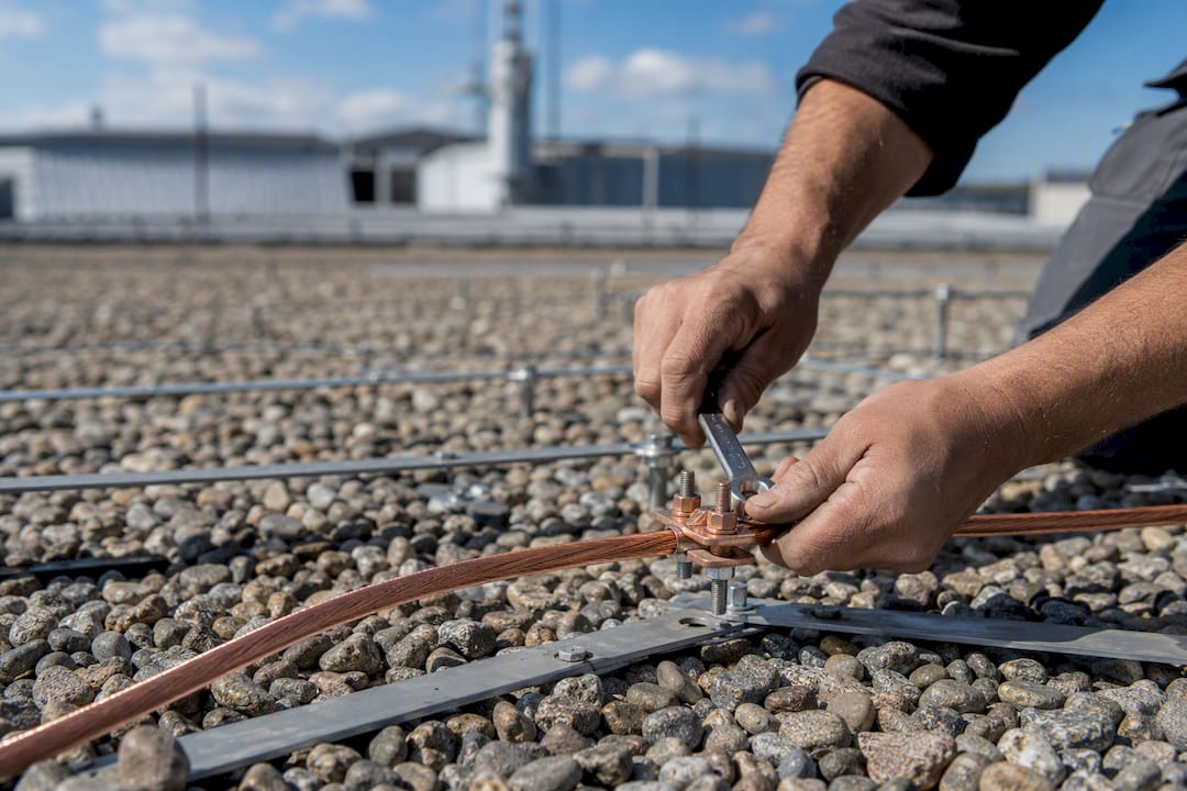
- Fasten bonding conductors securely at both ends. A loose lug defeats the purpose of the whole connection.
- Bring cable tray earths, structural steel, and SPD grounds into the same bonding bar or mesh rather than letting each subsystem ground independently.
For larger footprints, mesh interconnection outperforms a single star-point ground. A meshed network gives lightning current multiple paths to dissipate, which matters because a single ground rod under high-frequency lightning current behaves very differently than it does under 50/60 Hz fault current. Soil resistivity, rod depth, and interconnection density all factor into how well a mesh actually equalizes potential across a large building or industrial site.
Surge Protective Devices: Selection, Placement, and Wiring
SPDs come in three types, and each one has a job the others don’t do. Type 1 devices handle direct or partial lightning current at the service entrance, where the building’s main earthing system meets the incoming supply. Type 2 devices sit at distribution boards (your TGBT) and knock down the residual voltage that gets past the Type 1 stage. Type 3 devices protect specific sensitive equipment right at the point of use. NF EN 61643-11 governs the selection and testing criteria for these low voltage SPDs.
Placement follows the energy path. Type 1 goes where lightning current first enters the electrical system. Type 2 goes at each distribution board downstream. Type 3, or signal arresters, belong at building entry for any communication or control lines, and again close to the specific device if that device is particularly sensitive or expensive to replace.
- Wire SPD bonding leads as short and as straight as physically possible, following the low inductance approach detailed in Chint Power Systems’ installation guidance.
- Coordinate clamping voltages between SPD stages. A Type 2 device with a clamping voltage too close to your Type 1 device can leave a “coordination gap” that lets residual energy through unclamped.
- Never let excess SPD lead length hide behind a panel door. Coiled slack adds inductance exactly where you need the lowest impedance path.
- For metallic armor on communication cables, ground it at the building entry point and pair it with a signal arrester rather than leaving it floating.
Pro Tip:If two SPD stages are both rated to clamp around the same voltage, you don’t have redundancy. You have a race condition. Check the manufacturer’s coordination tables before final wiring, not after.
Installation Practices That Cut Inductance and Mechanical Risk
Every bend, coil, and loose fastening in a grounding conductor adds impedance that fights against you exactly when lightning current needs a clear path out. Coiling excess ground cable, rather than trimming it to length, dramatically increases inductive impedance and can render an otherwise well-sized conductor nearly useless during a strike.
- Fasten exposed downleads and main conductors at regular intervals, roughly every meter where the run is exposed to wind and thermal movement, consistent with construction guidance in the LPI-175 technical standard.
- Use long, smooth bends rather than sharp corners. A radius greater than 18 inches, where the routing space allows it, keeps the current path close to a straight line instead of forcing it through a sharp electrical discontinuity.
- Never store slack as a coil or spiral. If a conductor run comes up short, extend it properly rather than looping the extra length, which turns the conductor into an inductor.
- Keep grounding conductors out of metallic conduit and away from tight metallic clamps that encircle them completely, since both configurations concentrate magnetic coupling right where you’re trying to dissipate current cleanly.
These aren’t cosmetic details. They determine whether a conductor sized correctly on paper actually performs the way its cross-section suggests it should.
Conductor Materials: Copper, Aluminum, and Construction Choices
Copper remains the standard choice for downleads and bonding conductors because of its conductivity and corrosion resistance, particularly in coastal or industrial atmospheres where aluminum’s oxide layer can create long-term connection problems. Aluminum works where weight or cost drives the decision, but it demands more careful connection hardware to avoid galvanic corrosion at copper interfaces.
- Stranded or rope-lay construction outperforms solid conductors for lightning current specifically, because high-frequency current travels along the conductor’s surface, and more strands mean more surface area.
- Rope-lay construction also flexes more easily around the long-radius bends installation best practices call for.
- For buried grounding conductors, stranded copper generally handles soil movement better than solid rod, though cad-weld connections work well with either for driven ground rods.
- Structural steel and rebar can serve as part of the bonding network when properly bonded and continuous, but they need supplementary bonding jumpers at every structural joint that isn’t inherently a solid electrical connection.
Common Field Mistakes to Catch Before Commissioning
Most lightning protection failures aren’t design failures. They’re installation shortcuts that never got caught before the system went live.
- Separate, unconnected earth networks on the same site, often left over from separate contractors working different systems.
- Coiled excess grounding conductor tucked behind a panel because it looked neater than trimming it.
- Shields bonded at both ends without coordination, which can create a ground loop instead of the intended drain path.
- SPD bonding leads that run several feet because the SPD was mounted wherever there was panel space, not wherever the lead could be shortest.
- Mixed BT and TBT cables in the same tray with no partition, because the tray “had room.”
Pro Tip:Photograph every SPD bonding lead and every shield termination before you close up panels. It takes five minutes and it’s the fastest way to catch a coiled lead or an unbonded shield before it becomes a callback.
Multiple independent earth networks, missing bonding documentation, or repeated SPD failures at the same site are escalation triggers. They point to a systemic gap, not a one-off oversight.
Indelec’s Field Checklist and Corrective Approach
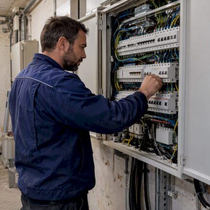
A short survey before sign-off catches most of what matters: tray separations, equipotential bonding continuity, SPD bonding lead lengths, shield terminations, and whether any communication cable carries metallic armor that needs grounding at entry.
- Where soil resistivity makes standard earthing insufficient, deep earth grounding drilling reaches lower resistivity strata that surface rods can’t touch.
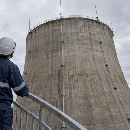
- Sites with weak or aging conductor networks often need redundant downleads engineered into the overall lightning protection system.
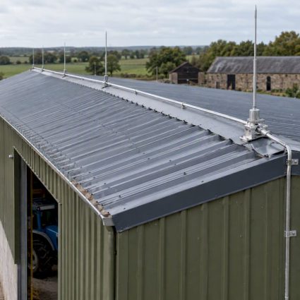
- Air termination integration, including Prevectron® terminals, ties directly into the routing and bonding plan rather than sitting as a separate afterthought.
- SPD coordination and certification close the loop between design intent and what actually gets installed.
What Actually Separates a Good Installation From a Vulnerable One
Most lightning protection advice treats routing, bonding, and SPD selection as three separate topics with three separate specialists. That’s backwards. A perfectly sized SPD wired with an 80 cm bonding lead performs worse than a smaller SPD wired with a 15 cm lead, and a beautifully designed grounding mesh means nothing if a contractor coiled six feet of slack into a junction box because it looked tidy.
The conventional advice focuses heavily on component selection: which SPD type, which conductor gauge, which air terminal. Component selection matters less than most engineers assume once you’re above a reasonable baseline. What actually determines whether a system performs during a real strike is the geometry of the installation: lead lengths, bend radii, and whether every ground point on site talks to every other ground point.
If you take one thing from a technical review of a site, make it this: walk the bonding network with a continuity tester before you walk it with a spec sheet. The spec sheet tells you what should work. The continuity test tells you what will.
— INDELEC
Get a Site-Specific Lightning Protection Plan From Indelec
Reading the rules is one thing. Verifying that a specific building, with its specific tray layout, soil resistivity, and legacy wiring, actually meets them is another. Indelec designs and installs complete lightning protection systems, air terminals, grounding networks, and SPD coordination, engineered around IEC 62305 principles rather than generic separation rules applied without site data.

If your facility has multiple independent earth networks, aging downleads, or SPDs that have failed more than once, that’s a system-level problem, not a component problem. Indelec’s lightning protection system application service starts with a site survey covering exactly the checklist points in this article: tray separation, bonding continuity, lead lengths, and shield terminations. Where soil conditions demand it, Indelec’s deep earth grounding drilling reaches the resistivity a standard rod pattern can’t. Request a site assessment and get a documented plan built around your actual installation, not a generic checklist.
Sources
- Inverter best installation practices — Chint Power Systems
- Paratronic — Secure your installations against lightning and surges
- Effets sur les installations électriques