Key Factors in Lightning System Design for Engineers

TL;DR:
- Lightning protection system design involves selecting and integrating components based on risk assessments to prevent damage and protect lives. Proper siting of air terminals, routing of down conductors, and precise grounding are critical for safety and compliance with IEC standards. Regular testing of ground resistance and system components ensures ongoing effectiveness throughout the structure’s lifespan.
Lightning protection system design is defined as the structured process of selecting, sizing, and integrating components to safely intercept and dissipate lightning current before it damages a structure or its occupants. The key factors in lightning system design begin with a risk-based selection of the appropriate Lightning Protection Level (LPL) per IEC 62305, followed by correct specification of lightning system components including air terminals, down conductors, grounding electrodes, equipotential bonding, and surge protective devices (SPDs). Lightning protection is a regulatory requirement that engineers and architects must satisfy to demonstrate compliance to insurers and regulators. Getting these decisions right at the design stage prevents costly retrofits and, more critically, prevents loss of life.
1. How to determine the appropriate Lightning Protection Level
The Lightning Protection Level is the single most consequential decision in designing effective lightning systems. It governs every dimensional parameter that follows, from the radius of the rolling sphere used to define protection zones to the spacing of down conductors.
IEC 62305 defines four LPL categories with distinct rolling sphere radii:
- LPL I: 20 m radius. Applies to structures with the highest risk, such as hospitals, data centers, and facilities storing explosive or flammable materials.
- LPL II: 30 m radius. Appropriate for commercial buildings with significant occupancy or high economic value.
- LPL III: 45 m radius. Covers standard industrial and commercial structures.
- LPL IV: 60 m radius. The lowest protection class, suited to structures with minimal risk to life or low economic consequence.
A smaller rolling sphere radius means the protection zone is tighter and the system must be more densely configured. That directly increases material and installation cost, which is why accurate LPL selection matters from a budget standpoint as much as a safety one.
The risk assessment methodology under IEC 62305 requires site-specific lightning density data drawn from IEC 62858 rather than broad regional averages. Regional averages can understate or overstate actual ground flash density by a significant margin depending on local topography. Factors that drive the risk calculation include structure height, occupancy type, the nature of contents (flammable, explosive, irreplaceable), and the economic consequences of a strike. A warehouse storing non-hazardous goods in a low-density lightning zone may justify LPL IV. A telecom tower in a high-density zone with critical communications equipment demands LPL I or II.
2. Critical lightning system components and their design specifications
A compliant external lightning protection system requires four core elements working together. Air terminations, at least two down conductors, grounding electrodes, and equipotential bonding must all be present and correctly specified for a non-isolated system.
Air termination systems
Air terminals intercept the lightning strike before it contacts the structure. Three placement methods apply depending on structure geometry:
- Rolling sphere method: The most universally applicable. A virtual sphere of the LPL-defined radius is rolled over the structure. Any point the sphere touches is a candidate for an air terminal.
- Protection angle method: Simpler to apply on straightforward structures. A cone of protection is projected from the tip of the rod at an angle determined by the LPL and rod height.
- Mesh method: Used on flat or gently sloping roofs. Conductors are laid in a grid pattern with mesh dimensions specified by the LPL (10 m x 10 m for LPL I, up to 20 m x 20 m for LPL IV).
Down conductors
Down conductors carry the intercepted current from the air terminal to the grounding system. Routing quality directly affects system safety. Minimum two down conductors are required for non-isolated systems, and they must be distributed around the building perimeter to divide the current and reduce the magnetic field inside the structure.
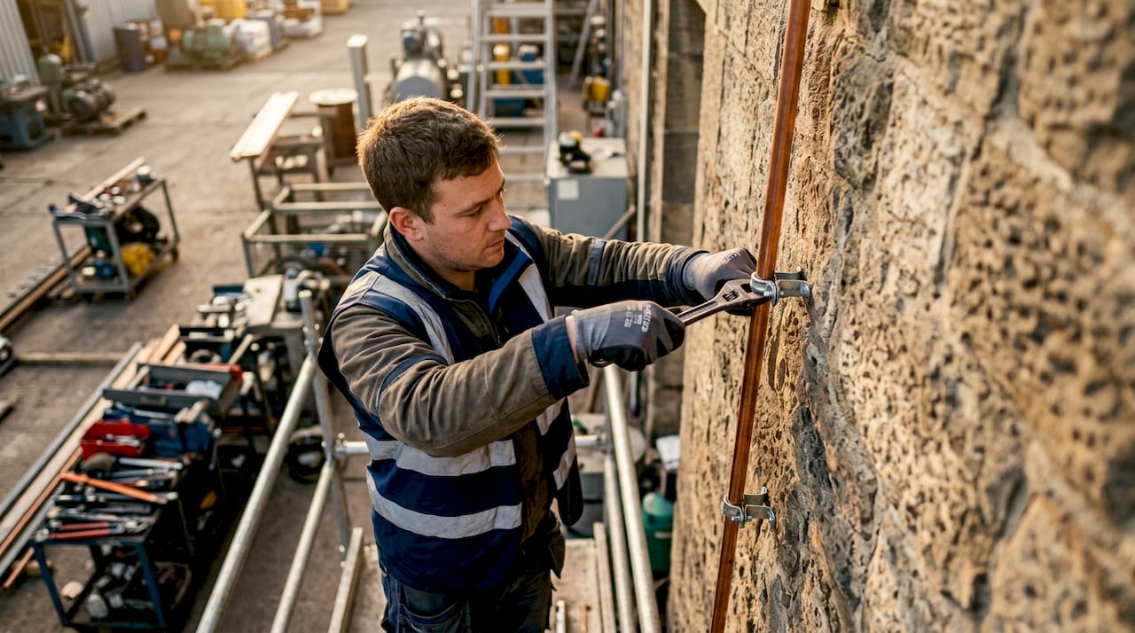
Pro Tip:Route down conductors on the exterior of the building where possible and keep them away from windows, doors, and internal metallic services. This reduces the risk of side-flash arcing to internal conductors during a strike.
Grounding electrodes
The grounding system dissipates the lightning current into the earth. Electrode configuration depends on soil resistivity, which must be measured using the Wenner 4-pin method before design is finalized. Options include single vertical rods, ring electrodes around the building perimeter, and radial systems extending outward from the structure.
Surge protective devices
SPDs protect power and communication lines from transient overvoltages caused by both direct strikes and nearby ground flashes. SPD selection must coordinate with the overall lightning protection system design per IEC standards. Placing SPDs at the service entrance and at sensitive equipment panels provides layered protection.
3. Best practices for conductor routing and grounding system design
Conductor routing is where many otherwise compliant designs fail in practice. The physical path of the down conductor determines how much surge impedance the system presents and whether dangerous arcs can jump to adjacent metallic services.
Down conductor routing requires a minimum 20 cm bend radius and the fewest possible direction changes. Sharp bends increase inductance, which raises the voltage across the conductor during a fast-rising lightning current pulse. That elevated voltage is what drives side-flash arcing to nearby pipes, conduits, and structural steel.
Pro Tip:When routing conductors through building corners, use a gradual sweep rather than a right-angle bracket. The difference in surge impedance between a 20 cm radius bend and a 5 cm radius bend is measurable and directly affects side-flash risk.
Separation distance from internal metallic services is a frequently underestimated design factor. IEC 62305-3 provides the formula for calculating the required separation distance based on LPL, conductor length, and the type of material separating the conductors. Where that separation cannot be maintained, equipotential bonding is the required solution.
The grounding system design must account for soil resistivity measured at the actual site. High resistivity soils require larger electrode arrays or chemical enhancement to reach a target ground resistance below 10 Ω. The table below summarizes common grounding configurations and their typical applications:
| Electrode type | Typical application | Notes |
|---|---|---|
| Single vertical rod | Low resistivity soils | Simplest installation; may not meet 10 Ω target alone |
| Ring electrode | Perimeter of buildings | Effective for large footprint structures |
| Radial system | High resistivity soils | Multiple arms extend outward to increase contact area |
| Chemical enhancement | Rocky or very dry soils | Reduces resistivity around electrode; requires periodic recharge |
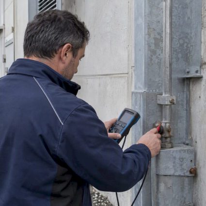
Ground resistance must be verified at commissioning and retested every 3–5 years. Soil conditions change with drought, construction activity, and seasonal moisture variation. A system that passed commissioning can drift out of compliance without periodic verification.
Bimetallic connections deserve specific attention. Galvanic corrosion between copper and aluminum is a common installation oversight that causes high-impedance joints and eventual system failure. Approved bimetallic connectors eliminate this risk and extend system service life. Never join dissimilar metals with a standard compression lug.
4. Surge protection and equipotential bonding
Equipotential bonding is the practice of connecting all metallic building elements to a common reference potential. IEC 62305-3 Clause 6 defines the bonding requirements, which include structural steel, metallic pipe systems, cable trays, HVAC ductwork, and any other conductive element that enters or runs through the structure.
The hazard that bonding prevents is the side flash. During a direct strike, the down conductor reaches a very high potential relative to nearby metallic services. If the voltage difference exceeds the breakdown strength of the intervening air or material, an arc jumps between them. That arc carries enough energy to ignite fires, damage equipment, and injure personnel. Bonding eliminates the voltage difference before it can develop.
Practical bonding considerations for engineers and architects include:
- Bonding bars: Install a main bonding bar at each level of a multi-story structure, connected to the down conductors and to all metallic services at that level.
- Expansion joints: Use flexible bonding conductors across structural expansion joints to maintain continuity during thermal movement.
- Incoming services: Bond all metallic incoming services (water, gas, telecommunications, power) at the point of entry to the building.
- Isolated metallic objects: Large metallic objects on rooftops, such as HVAC units and antenna masts, must be bonded to the air termination network, not left floating.
SPDs complement bonding by handling the transient overvoltages that travel on power and signal cables. A properly rated and placed SPD at the service entrance limits the voltage that reaches internal equipment. A second tier of SPDs at the equipment panel provides additional protection for sensitive electronics. The two tiers must be coordinated so the upstream device clamps voltage before the downstream device is called upon to act.
Maintenance of bonding and SPD systems requires periodic visual inspection for corrosion at bonding connections and functional testing of SPDs. Most SPDs include a status indicator, but visual inspection alone is not sufficient. SPDs that have absorbed multiple surge events may show no external damage while their clamping performance has degraded significantly.
Key Takeaways
Effective lightning protection requires accurate LPL selection, compliant component integration, and verified grounding performance from the first day of commissioning through the life of the structure.
| Point | Details |
|---|---|
| LPL selection drives all design parameters | Use IEC 62305 risk assessment with site-specific IEC 62858 lightning density data, not regional averages. |
| Four components are non-negotiable | Air terminals, down conductors, grounding electrodes, and equipotential bonding must all be present and correctly specified. |
| Conductor routing affects safety directly | Maintain a minimum 20 cm bend radius and required separation distances to prevent side-flash arcing. |
| Grounding must be tested periodically | Verify ground resistance at commissioning and every 3–5 years; soil conditions change and can push systems out of compliance. |
| SPDs require coordination and maintenance | Select SPD ratings that coordinate with the overall system and inspect them regularly, since degraded devices may show no visible damage. |
What Indelec has learned from decades of infrastructure projects
The most consistent gap we see in lightning protection designs is not a missing component. It is the use of regional lightning density averages instead of site-specific data. A project in a valley between two ridges can have a ground flash density two to three times higher than the regional figure suggests. Designing to the average means the system is undersized from day one.
The second pattern we see repeatedly is inadequate conductor separation from internal metallic services, particularly in retrofit projects where the building was not designed with lightning protection in mind. Engineers often accept the available routing rather than pushing back on the architectural constraints. The result is a system that passes a paper review but creates real side-flash risk in practice.
Certified components matter more than engineers sometimes assume. A connector that looks correct but lacks the appropriate certification for the LPL can introduce a high-impedance joint that compromises the entire current path. We have seen this failure mode in systems that were otherwise well-designed. The fix is straightforward: specify certified components from the start and verify them during installation inspection.
Budget pressure is real on infrastructure projects. The place to find savings is not in conductor sizing or grounding electrode count. It is in early-stage design coordination that avoids expensive rerouting later. A well-routed system costs less to install and less to maintain than one that was value-engineered at the wrong stage.
— Indelec
Indelec’s support for compliant lightning protection projects
Indelec has been developing and installing certified lightning protection systems since 1955, with a full range of components and services built around IEC 62305 compliance. Every project starts with a site-specific risk assessment that uses actual lightning density data, not regional approximations.

Indelec’s engineering team provides customized design support covering LPL selection, component specification, conductor routing review, and grounding system design for soil conditions ranging from standard clay to high-resistivity rock. The company also offers technical training programs for engineers and architects who want to build internal competency on lightning protection standards. For project-specific guidance, Indelec’s risk assessment and maintenance services cover the full system lifecycle from initial design through periodic testing.
FAQ
What is the difference between LPL I and LPL IV?
LPL I uses a 20 m rolling sphere radius and applies to the highest-risk structures, while LPL IV uses a 60 m radius for low-risk applications. A smaller radius means tighter protection zone geometry and a more densely configured system.
How many down conductors does a building need?
A non-isolated lightning protection system requires a minimum of two down conductors distributed around the building perimeter. The actual number increases with building size and LPL requirements.
What ground resistance target should engineers design to?
The standard target for ground resistance is below 10 Ω, verified using the Wenner 4-pin soil resistivity test method. High-resistivity soils may require larger electrode arrays or chemical enhancement to reach this target.
Why does conductor bend radius matter in lightning protection?
A bend radius below 20 cm increases inductance in the conductor, which raises voltage during a fast-rising lightning current pulse and increases the risk of side-flash arcing to nearby metallic services.
How often should a lightning protection system be tested?
Ground resistance and system integrity should be verified at commissioning and retested every 3–5 years. Soil conditions, corrosion, and construction activity can all degrade performance between inspections.