What Is Electrical Bonding? A Guide for Facility Pros
TL;DR:
- Electrical bonding involves intentionally connecting metallic parts to create an equipotential zone that prevents dangerous voltage differences. It differs from grounding, which stabilizes voltage levels and dissipates surges, while bonding provides a fault current path essential for trip protection. Proper installation, conductor sizing, and proximity to service entry are critical for safety and compliance, especially in high-risk areas like bathrooms and industrial facilities.
Electrical bonding is defined as the intentional connection of exposed and extraneous conductive parts to create an equipotential zone, eliminating dangerous voltage differences that cause electric shock. Every metal pipe, structural steel beam, and equipment enclosure in your facility is a potential shock hazard unless it shares the same electrical potential as everything around it. Standards like NEC Article 250 and BS 7671 mandate bonding precisely because unconnected metal parts can carry lethal voltage during a fault. Understanding the electrical bonding definition, how it differs from grounding, and what proper installation requires is non-negotiable for facility managers, contractors, and engineers responsible for electrical safety and compliance.
What is electrical bonding and how does it work?
Electrical bonding is the deliberate practice of connecting all accessible conductive parts in an installation so they reach the same electrical potential. When a fault occurs, any two metal surfaces at different potentials create a voltage difference across whatever connects them, including a person’s body. Bonding eliminates that difference by tying all conductive parts together through a low-impedance conductor path.
The mechanism is straightforward. A bonding conductor connects each extraneous conductive part, such as a gas pipe, water pipe, or structural steel column, to the Main Earthing Terminal (MET). From the MET, the system connects to the earth electrode. The result is an equipotential bonding zone where all metal surfaces rise and fall together in voltage, so no dangerous potential difference exists between them during normal operation or a fault event.
NEC Article 250 treats bonding as a distinct function from grounding. Under NEC 2026 250.4, bonding creates an effective ground-fault current path by connecting metal parts so that protective devices can clear faults. This is the core of how electrical bonding works in practice. Without a properly bonded fault current path, a circuit breaker or fuse may never see enough current to trip, leaving energized metal exposed to anyone who touches it.
Two types of bonding apply in most facilities. Main protective bonding connects all extraneous conductive parts entering the building to the MET. Supplementary bonding creates localized equipotential zones in high-risk areas, such as bathrooms, where multiple conductive surfaces are in close proximity and a person is likely to be in contact with more than one at a time.
Electrical bonding vs grounding: what’s the difference?
Bonding and grounding are complementary but serve entirely different functions. Confusing them is one of the most common errors in facility electrical work, and the consequences range from failed inspections to fatal shock incidents.
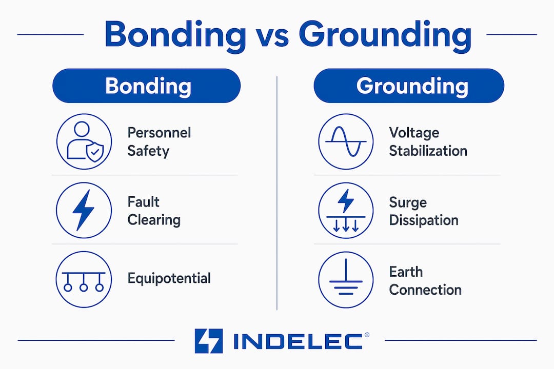
Grounding (also called earthing) connects the electrical system to the earth to stabilize voltage references and dissipate lightning surges and transient overvoltages. The earth connection provides a reference point for the system, not a fault-clearing path. Earth is a poor conductor for fault current, which is why grounding alone cannot reliably trip a protective device during a ground fault.
Bonding provides the actual fault-clearing path. When a live conductor contacts a bonded metal enclosure, the bonding conductor carries fault current back to the source through a low-impedance path, generating enough current to trip the breaker or blow the fuse. Without bonding, that fault current has no reliable return path, and the enclosure stays energized.
| Function | Grounding | Bonding |
|---|---|---|
| Primary purpose | Voltage stabilization and surge dissipation | Fault current path and equipotential zone |
| Connects to | Earth electrode | Extraneous conductive parts and MET |
| Clears faults? | No | Yes, by enabling overcurrent device operation |
| Governed by | NEC 250.4, BS 7671 Part 5 | NEC 250.4, BS 7671 Part 5 |
| Failure consequence | Voltage instability, surge damage | Energized metal, shock hazard, failed fault clearing |
BS 7671 makes this distinction explicit: do not earth parts that should be bonded and vice versa. Each function requires its own correctly sized conductor and connection point. Treating them as interchangeable creates systems that satisfy neither requirement.
Pro Tip:When reviewing an existing installation, check that the bonding conductor connects to the MET and not directly to the earth electrode. A direct connection to the electrode bypasses the fault current path through the protective device, which defeats the purpose of bonding entirely.
Key components and installation requirements
Effective bonding depends on conductor sizing, connection location, and coverage of all extraneous conductive parts. Getting any one of these wrong reduces the system’s ability to create a true equipotential zone.
Main protective bonding conductors
BS 7671 recommends sizing main protective bonding conductors at half the cross-sectional area of the main earthing conductor, with a minimum of 6 mm² and a maximum of 25 mm². This sizing range reflects the balance between carrying enough fault current to trip protective devices and practical installation constraints. Undersized conductors create high-impedance paths that limit fault current and may prevent protective devices from operating within the required disconnection time.
Supplementary bonding locations
Supplementary bonding applies in bathrooms, shower rooms, and other locations where a person can simultaneously contact multiple conductive surfaces. In a bathroom, this means connecting metal pipes, towel rails, electric shower casings, and any other accessible metalwork to create a local equipotential zone. The logic is that even if a fault raises the potential of one surface, all connected surfaces rise together, so no shock current flows through the person.
Connection proximity to service entry
Inspection procedures consistently identify one critical installation requirement: main protective bonding must connect to extraneous conductive parts as close as possible to where they enter the facility. A gas pipe bonded 10 meters inside the building still has 10 meters of unbonded metal at the entry point, which can carry a different potential during a fault. Proximity to the service entry is not a preference. It is the technical requirement that makes the equipotential zone work.
Extraneous conductive parts requiring bonding
The following parts require main protective bonding in most commercial and industrial facilities:
- Metal water supply pipes and hot water systems
- Gas supply pipes and associated metalwork
- Structural steel columns and beams accessible within the installation
- Metal ducting for HVAC systems
- Central heating pipework and radiators
- Metal cable trays and conduit systems not already part of the circuit protective conductor
Pro Tip:During facility audits, use a low-resistance ohmmeter to verify bonding conductor continuity from each extraneous part back to the MET. Resistance above 0.05 ohms on a bonding conductor typically indicates a poor connection or undersized conductor that needs immediate attention.
You can find detailed guidance on grounding conductor sizing and compliance testing in Indelec’s published resources on grounding standards.
Safety benefits of electrical bonding in facility management
The importance of electrical bonding comes down to one measurable outcome: it keeps people alive during electrical faults. Protective bonding is a mandatory safety requirement in electrical installations, yet it remains one of the most frequently overlooked elements during facility upgrades and renovations.
The benefits of electrical bonding operate on two levels. The first is immediate personnel protection. By equalizing potentials across all accessible metal surfaces, bonding eliminates the voltage difference that drives current through a person’s body. A worker touching a bonded enclosure and a bonded pipe simultaneously experiences no potential difference between the two surfaces, so no shock current flows.
The second level is system reliability. Bonding enables overcurrent protective devices to operate correctly during ground faults. When fault current has a low-impedance return path through bonding conductors, it reaches the level required to trip a circuit breaker within the disconnection time specified by NEC or BS 7671. Without that path, the fault may persist for seconds or minutes, heating conductors, igniting insulation, and exposing personnel to sustained shock risk.
Practical benefits for facility managers include:
- Reduced liability exposure from electrical shock incidents caused by unbonded metalwork
- Faster fault clearing that limits arc flash energy and equipment damage
- Simplified maintenance because bonded systems are easier to test and verify during periodic inspections
- Compliance with NEC Article 250 and BS 7671, which is required for insurance coverage and occupancy permits in most jurisdictions
- Reduced electromagnetic interference in facilities with sensitive electronic equipment, since bonding limits circulating currents on metal structures
For industrial facilities with distribution center safety zones, bonding is a foundational requirement before any safety zone designation is meaningful. A safety zone around unbonded metalwork provides no actual protection during a fault.
Common misconceptions about electrical bonding
The most persistent misconception is that bonding means connecting any metal parts with any wire. Effective bonding requires engineered conductor sizing, correct placement, and verified connections to specific termination points. A random wire between two pipes does not create a compliant equipotential zone.
Three errors appear repeatedly in facility inspections:
- Conductor undersizing: Using 2.5 mm² wire where 10 mm² is required creates a high-impedance path that limits fault current and may prevent breaker operation.
- Wrong termination point: Bonding conductors connected to circuit protective conductors rather than the MET create parallel fault paths that complicate fault analysis and may not provide the required equipotential zone.
- Omission of extraneous parts: Contractors often bond water pipes but miss gas pipes, structural steel, or HVAC ducting. Any unbonded conductive part can carry a different potential during a fault.
Bonding is also not a substitute for proper earthing. The two systems work together. Bonding equalizes potentials between accessible parts but does not carry primary fault currents or provide the voltage reference function that earthing delivers. A facility with bonding but no earthing has no voltage reference and no surge dissipation path. A facility with earthing but no bonding has no reliable fault-clearing path and no equipotential protection.
Pro Tip:Schedule bonding verification as part of every electrical periodic inspection. Check that all extraneous conductive parts identified in the original installation schedule are still bonded, since renovations frequently cut or remove bonding conductors without replacement.
For facilities subject to lightning protection requirements, bonding takes on additional significance. Lightning current entering through a metal service pipe or structural steel can cause catastrophic potential differences if those parts are not bonded to the lightning protection system’s equipotential bonding network.
Key takeaways
Electrical bonding is the technical foundation of personnel protection in any facility electrical system, and it works only when conductors are correctly sized, correctly placed, and connected to the right termination points.
| Point | Details |
|---|---|
| Bonding definition | Intentional connection of conductive parts to create an equipotential zone and eliminate shock voltage. |
| Bonding vs grounding | Grounding stabilizes voltage; bonding provides the fault current path that trips protective devices. |
| Conductor sizing | BS 7671 requires minimum 6 mm² and maximum 25 mm² for main protective bonding conductors. |
| Installation location | Bond extraneous parts as close as possible to the service entry point for effective equipotential zones. |
| Common failure mode | Omitting extraneous parts or undersizing conductors leaves unbonded metal that can carry lethal voltage. |
Indelec’s perspective on bonding as a safety foundation
After decades of working on electrical protection systems across industrial and infrastructure facilities, the pattern Indelec sees most often is this: bonding gets treated as an afterthought. It gets installed after the main electrical work is complete, by whoever is available, with whatever conductor is on hand. Then it fails an inspection, or worse, it fails during a fault.
The facilities that get bonding right integrate it into the design phase. They identify every extraneous conductive part on the drawings before a single cable is pulled. They specify conductor sizes based on the earthing conductor cross-section, not on what is convenient. They locate the MET and plan bonding routes to service entry points before the walls are closed.
What we have also observed is that bonding failures are disproportionately common in facilities that have undergone renovation. A contractor cuts a bonding conductor to route new pipework and does not replace it. A new HVAC duct gets installed without bonding because the mechanical contractor does not consider it their responsibility. The result is a facility that passed its original inspection and now has multiple unbonded conductive parts that no one knows about.
The integration of bonding with lightning protection systems is an area where Indelec sees significant gaps. A lightning protection system that terminates at a ground electrode without bonding to internal metalwork creates exactly the kind of potential difference that causes side flash and equipment destruction. Bonding the lightning protection system to the facility’s equipotential network is not optional. It is the mechanism that makes the whole system work as designed.
Facility managers who treat bonding verification as a routine maintenance task, rather than a one-time installation check, consistently have fewer electrical incidents and faster fault resolution times. That is not a coincidence.
— Indelec
How Indelec supports compliant bonding and grounding systems
Indelec has specialized in electrical protection since 1955, and grounding and bonding system integrity sits at the core of every installation the company designs and certifies.

For facility managers and contractors who need verified, compliant bonding systems, Indelec provides technical consulting, installation services, and certification for grounding and equipotential bonding networks. The company’s Prevectron 3 lightning protection system integrates directly with facility bonding networks to provide complete protection from lightning-induced potential differences. Indelec also offers lightning protection system design that incorporates equipotential bonding as a core component, not an add-on. Contact Indelec to assess your facility’s bonding compliance and identify gaps before the next inspection or fault event.
FAQ
What is the electrical bonding definition under NEC?
Under NEC Article 250, electrical bonding is the connection of metal parts to create an effective ground-fault current path that enables overcurrent protective devices to clear faults. It is treated as a distinct function from grounding, which connects the system to earth for voltage stabilization.
Why is electrical bonding required in bathrooms?
Bathrooms require supplementary bonding because a person can simultaneously contact multiple conductive surfaces, such as metal pipes and shower casings, while standing on a wet floor. Bonding connects all those surfaces to a local equipotential zone so no shock voltage exists between them.
Can bonding replace grounding in an electrical installation?
Bonding cannot replace grounding. Bonding equalizes potentials between accessible conductive parts but does not provide the voltage reference or surge dissipation function that earthing delivers. Both systems are required and serve distinct safety functions under NEC and BS 7671.
What conductor size is required for main protective bonding?
BS 7671 specifies main protective bonding conductors at half the cross-sectional area of the main earthing conductor, with a minimum of 6 mm² and a maximum of 25 mm². Undersized conductors create high-impedance paths that limit fault current and may prevent protective devices from operating correctly.
How often should electrical bonding be inspected?
Bonding should be verified during every periodic electrical inspection, and after any renovation or modification that involves metalwork, pipework, or HVAC systems. Renovations frequently cut or disconnect bonding conductors without replacement, creating unbonded parts that carry shock risk.