Essential grounding standards: ensure compliance and safety

TL;DR:
- Effective grounding in industrial facilities requires understanding layered standards like NEC 250, NFPA 780, NFPA 77, and IEEE 142, ensuring comprehensive safety and system reliability. Proper bonding and electrode interconnections prevent hazardous voltage differences during lightning events, which is critical for protecting equipment and personnel. Accurate documentation and ongoing management are essential for compliance, inspections, and adapting the grounding system to operational changes.
Grounding an industrial or commercial facility involves far more than pulling a single code off the shelf. Most facility managers assume one document covers their obligations, but the reality is a layered web of mandatory codes and recommended engineering practices, each addressing a different failure mode and risk scenario. Miss even one nuance, and you can face failed inspections, uninsured liability, or worse, a catastrophic arc flash or fire triggered by a lightning event. This article gives you a clear, practical framework for navigating NEC Article 250, NFPA 780, NFPA 77, IEC 62305-3, IEEE Std 142, and related standards, with special focus on the bonding and documentation requirements that trip up even experienced engineers.
Table of Contents
- Understanding the primary grounding standards for industrial facilities
- How lightning protection standards connect with other grounding requirements
- Interconnection and bonding: The cornerstone of compliance
- Documentation and practical compliance: What inspectors look for
- Why compliance isn’t just about checking boxes: Our expert take
- Take the next step: Indelec solutions for compliant facility grounding
- Frequently asked questions
Key Takeaways
| Point | Details |
|---|---|
| Layer multiple standards | Compliance demands understanding and applying NEC, NFPA, IEEE, and—where relevant—API or IEC standards together. |
| Bond all grounding electrodes | Interconnecting every grounding system prevents dangerous voltages and aligns with safety codes. |
| Prioritize clear documentation | Comprehensive drawings and records are essential for passing inspections and maintaining safety. |
| Engage engineering judgment | Go beyond minimum codes by applying IEEE best practices tailored to your facility’s unique risks. |
Understanding the primary grounding standards for industrial facilities
To understand why compliance is so nuanced, let’s first outline the major standards shaping grounding requirements in industrial and commercial applications.
Every facility engineer needs to hold at least five distinct standards in mind simultaneously. None of them fully replaces another. Together, they cover the complete spectrum of grounding scenarios your facility will encounter over its operational life.
The core standards at a glance:
- NEC Article 250 sets the fundamental mandatory requirements for electrical safety grounding and bonding in virtually every U.S. facility. It addresses service entrance grounding, equipment grounding conductors, grounding electrode systems, and bonding of metal parts. It is the floor, not the ceiling.
- NFPA 77 (Recommended Practice on Static Electricity) governs static charge control, relevant to any facility handling flammable liquids, powders, or gases. It focuses on preventing ignition through uncontrolled electrostatic discharge.
- NFPA 780 (Standard for the Installation of Lightning Protection Systems) is the U.S. controlling document for lightning protection design and installation, including air terminals, down conductors, and grounding electrode requirements specific to lightning events.
- API 2003 addresses static electricity hazards in petroleum operations, layering additional sector-specific guidance on top of NFPA 77 for refineries and tank farms.
- IEEE Std 142 and IEEE 3003.1 provide engineering methodology for industrial and commercial power system grounding. A practitioner reference lists NEC Article 250 as the fundamental framework for electrical grounding, NFPA 77 for static electricity, NFPA 780 for lightning protection, and API 2003 for petroleum facilities, and points to IEEE 142 for comprehensive industrial grounding design.
The critical distinction between mandatory codes and recommended practices matters here. NEC and NFPA 780 are adopted into law in most U.S. jurisdictions and carry legal weight. IEEE Std 142 is a recommended practice, meaning it does not carry direct legal force. However, IEEE recommended grounding practices provide the engineering methodology that bridges code minimums with real-world system performance, especially for complex configurations involving multiple power sources, significant fault current levels, or challenging soil conditions.
| Standard | Type | Primary scope | Applies to |
|---|---|---|---|
| NEC Article 250 | Mandatory code | Electrical safety grounding and bonding | All facilities |
| NFPA 780 | Mandatory code | Lightning protection installation | All structures at risk |
| NFPA 77 | Recommended practice | Static electricity control | Flammable/combustible environments |
| API 2003 | Recommended practice | Petroleum static ignition | Refineries, tank farms |
| IEEE Std 142 / 3003.1 | Recommended practice | Power system grounding methodology | Industrial and commercial power systems |
| IEC 62305-3 | International standard | Lightning protection grounding | International and global projects |
Key insight: Code compliance is commonly approached as a set of standards by application, not a single document. When you combine mandatory minimums with IEEE methodology, you build a system that survives the edge cases that generic codes never anticipated.
For facilities with lightning exposure concerns, understanding lightning protection grounding standards is an essential first step before your engineers begin any system design or retrofit.
How lightning protection standards connect with other grounding requirements
With the standards landscape mapped, let’s zoom in on the critical points where lightning protection grounding requirements merge with general facility and system grounding.
Lightning protection grounding is not a standalone system. This is where many projects go wrong. Engineers design an excellent electrical service ground, then bolt on a separate lightning protection ground as an afterthought. The result is two independent electrode systems that can develop dangerous voltage differences during a lightning event, destroying equipment and endangering personnel.
NFPA 780 and its coordination requirements:
U.S. DoD/WBDG guide specifications explicitly state compliance with NFPA 780 for lightning protection systems on federal facilities. NFPA 780 requires that all grounding electrodes serving a structure, whether they belong to the electrical service, the lightning protection system, the communication systems, or the antenna arrays, be bonded together into a single unified electrode system. Separate, isolated ground systems are never acceptable under this framework.
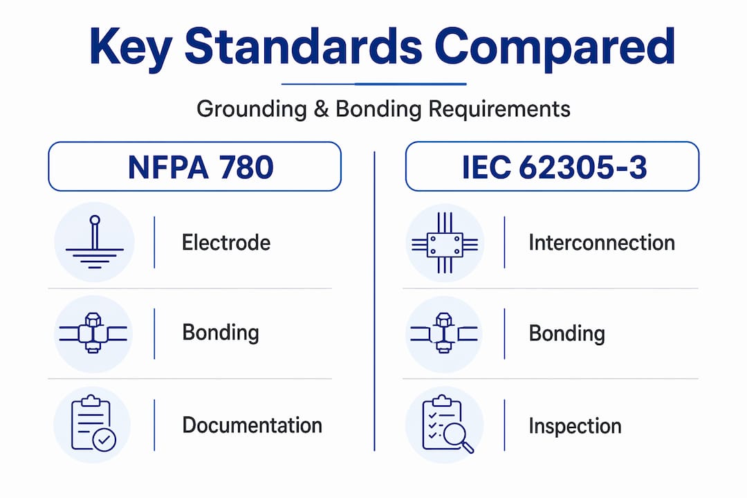
IEC 62305-3, the international counterpart, requires interconnection of building grounding electrode systems in a nearly identical fashion. For facilities operating under both U.S. and international project specifications, the requirements are functionally similar, though IEC 62305-3 introduces additional zone-based concepts around lightning protection zones (LPZ) that can affect where sensitive equipment is located and how surge protection devices are specified.
Integration requirements in practice:
- Identify every existing grounding electrode at your facility: utility service ground, building structural steel, communications, IT, and any existing lightning protection down conductors.
- Map all bonding connections already in place and confirm their conductor sizing meets both NEC Article 250 and NFPA 780 requirements for the expected fault and surge currents.
- Determine where new bonding connections are needed to tie the lightning protection electrode network to the main grounding electrode system.
- Specify the bonding conductor routing to avoid introducing unwanted current paths through areas housing sensitive instrumentation or control systems.
- Document all tie-in points on project drawings before installation begins.
Pro Tip: When integrating a new lightning protection grounding system with an existing service ground, run your bonding conductor as directly as possible. Every additional foot of conductor adds impedance, and at the high-frequency components present during a lightning discharge, impedance matters far more than DC resistance.
Explore lightning protection system applications to see how these interconnection principles are applied across industrial sites, data centers, and critical infrastructure. When your facility engineers engage early with these application frameworks, the integration work becomes far less expensive than retrofitting after installation.
| Requirement | NFPA 780 | IEC 62305-3 |
|---|---|---|
| Electrode interconnection | Required | Required |
| Bonding to utility ground | Required | Required |
| Surge protection coordination | Addressed | More detailed LPZ approach |
| Documentation of tie-in points | Required | Required |
| Conductor sizing guidance | Specified | Specified |
The importance of reliable lightning protection extends well beyond the air terminal on your rooftop. Getting the grounding and bonding right is what determines whether a lightning strike causes a brief transient or a week of production downtime.
Interconnection and bonding: The cornerstone of compliance
Now that we understand which codes and standards apply, it’s time to drill into the implementation: how different grounding systems are physically and electrically bonded together.
Bonding is the process of intentionally connecting two or more conductive systems together to establish electrical continuity and minimize voltage differences. It sounds straightforward. In practice, it is where most compliance failures occur, because it requires coordination between disciplines that rarely talk to each other: structural engineers, electrical engineers, IT infrastructure teams, and lightning protection specialists.
Why voltage differences are the real threat:
When a lightning strike hits a structure, it drives enormous amounts of charge into the grounding system in microseconds. If your lightning protection ground and your electrical service ground are separate, they momentarily reach different potentials. That potential difference appears across every piece of equipment connected to both systems simultaneously. The result is flashover damage inside control panels, destroyed input/output cards, and burned communication cables.
Common bonding pitfalls in industrial facilities:
- Missing bonding jumpers between structural steel columns and the main grounding electrode conductor, leaving large metallic sections floating at different potentials during fault conditions
- Inadequate conductor sizing on the grounding electrode conductor, especially after equipment upgrades increase available fault current without a corresponding grounding system review
- Poor mechanical connections at bonding points, including corroded lugs, improperly torqued fasteners, or connections made with incompatible metals causing galvanic corrosion over time
- Undocumented modifications, where additional equipment was grounded to the nearest convenient metal without verifying the path back to the main electrode system
- Parallel ground paths through instrumentation conduit or cable shields, which can inadvertently route high-frequency surge current through sensitive electronics
IEC 62305-3 and NFPA 780 both discuss bonding and interconnection requirements, and the NEC Article 250 requirements on the grounding electrode conductor connected to the service neutral conductor make the bonding obligation explicit at the service entrance. What many engineers miss is that this obligation extends to every new system added to the building over its service life.
Pro Tip: Create a grounding and bonding register as part of your facility management documentation. Every bonding point, its conductor size, installation date, and last inspection date should be tracked. This transforms an invisible, underground system into a manageable asset.
Best-practice strategies for bonding in complex facilities:
- Map all grounding electrode systems on a single facility drawing before any new installation begins, showing physical locations and connection paths
- Identify all sensitive equipment rooms and route bonding conductors to avoid introducing surge current into those areas
- Use listed bonding hardware and verify torque specifications for every connection
- Test ground resistance and bonding continuity after installation, and retain records of all test results for the inspection file
For guidance on safe grounding practices in complex industrial sites, engineering teams consistently find that a systematic approach at the design stage eliminates the most costly corrections. When you protect your facility through comprehensive bonding, you reduce not just lightning risk but the broader vulnerability to transient overvoltages from switching events and utility disturbances.
Documentation and practical compliance: What inspectors look for
Thorough interconnection is only part of compliance. Equally critical is demonstrable, documented adherence: what inspectors look for before signing off on your system.
Many technically excellent grounding systems fail inspection for purely administrative reasons. The system may be correctly installed, but if the documentation does not prove it, the inspector cannot pass it. This is especially true for government facilities, critical infrastructure, and projects subject to third-party commissioning.
What complete grounding compliance documentation must include:
- Project drawings showing all system components: air terminals with spacing and dimensions, down conductors with routing and sizing, grounding electrodes with location, depth, and configuration, and all bonding connections between systems.
- Ground resistance test reports: measured earth resistance for each electrode and for the combined electrode system, taken after installation and before final backfill where applicable.
- Bonding continuity test records: verification that all bonding jumpers and grounding electrode conductors are continuous and meet resistance requirements.
- Material compliance documentation: product data sheets and certifications for all listed components used in the system.
- Tie-in location details for additions to existing systems: when any modification extends or modifies the existing lightning protection or grounding system.
WBDG guide specifications for lightning protection systems include explicit project drawing requirements, mandating that drawings show locations and details of air terminals, down conductors, and grounding electrodes, along with the tie-in points for any additions to existing systems. Federal facility managers and their contractors who miss this requirement encounter significant delays at the commissioning stage.
“Lack of documentation is consistently cited by inspectors as the leading administrative reason for grounding system rejection, even when the physical installation is correct.”
Pro Tip: For any facility modification that touches a grounding or lightning protection system, update the as-built drawings within 30 days of completion. Deferred documentation almost always degrades into no documentation once the project team disperses.
Effective approaches to documenting lightning systems also help during insurance underwriting reviews and after any lightning damage event, where your documentation becomes the primary evidence for both the claims process and the cause-and-origin investigation.
Why compliance isn’t just about checking boxes: Our expert take
Here is what decades of lightning protection and facility grounding work teaches you: the facilities that experience the fewest failures are almost never the ones that simply met code minimums. They are the ones whose engineers asked “why does this requirement exist?” and then designed accordingly.
Code minimums are written for generic scenarios. They assume average soil resistivity, average fault current levels, and average equipment sensitivity. Your facility is not average. A chemical processing plant on coastal clay soil with high-power drives, sensitive process control instrumentation, and a petroleum storage yard in the same fence line presents a combination of risk factors that no single standard fully anticipates. This is precisely why layered guidance from NEC, NFPA, and IEEE exists, combining mandatory minimums with engineering best practices for soil resistivity, grounding impedance, and system-specific fault behavior.
The engineers we respect most treat IEEE Std 142 not as a nice-to-have reference but as their primary design tool, with the NEC and NFPA standards serving as the compliance floor below their engineered solution. This approach produces systems with measurably lower ground resistance, better transient performance, and longer service life without corrosion or mechanical failure at bonding points.
We also see that the facilities with the worst outcomes after lightning events are almost always the ones where grounding and bonding compliance was treated as a one-time checkbox at project handover, never revisited during plant expansions, equipment upgrades, or operational changes. A grounding system is not a static asset. It changes every time you add a transformer, extend a cable tray, or install new communications infrastructure. Treat it like the dynamic, living system it is, and your compliance posture stays current. Let it go undocumented for a few years, and you will spend considerably more recovering from an incident than you would have spent on annual reviews. For broader guidance on real-world electrical protection standards examples, we consistently see that proactive compliance programs outperform reactive ones both technically and financially.
Take the next step: Indelec solutions for compliant facility grounding
Navigating multiple grounding standards is demanding work, and the stakes are too high to rely on incomplete or outdated information. Indelec has been engineering compliant, high-performance lightning protection and grounding systems since 1955, working across industrial plants, commercial facilities, infrastructure projects, and government sites worldwide.

Whether you need a full grounding system assessment, technical consultation on bonding and electrode design, or specification support for a new project, Indelec’s team of specialists brings deep code expertise and field experience to every engagement. Our solutions are engineered to meet NEC, NFPA 780, and IEC 62305-3 requirements from the ground up, with complete documentation packages that stand up to inspection. From initial risk assessment through installation, commissioning, and ongoing maintenance, we support your full compliance lifecycle. Contact Indelec to discuss your facility’s grounding and lightning protection requirements with engineers who understand both the standards and the real-world conditions your system must survive.
Frequently asked questions
Which codes and standards must I follow for grounding an industrial facility?
You must follow NEC Article 250 for electrical grounding, NFPA 780 for lightning protection, and typically IEEE 142 or 3003.1 for engineering best practices; facilities handling flammable materials or petroleum also need NFPA 77 or API 2003.
What does NFPA 780 require for lightning protection grounding?
NFPA 780 requires proper installation of lightning protection systems with correct bonding and interconnection to all other building grounding electrode systems, ensuring no dangerous potential differences exist between them.
Why must all grounding systems be bonded together?
Bonding prevents hazardous voltage differences between separate electrode systems, which is required under IEC 62305-3 and NFPA 780 to protect both equipment and personnel during lightning events and fault conditions.
What documentation is essential for grounding compliance inspection?
You need project drawings with system components showing air terminals, down conductors, and grounding electrodes, along with ground resistance test certificates, bonding continuity records, and clearly marked tie-in locations for any system modifications.