Wind Turbine Lightning Protection: An Engineer’s 2026 Guide
TL;DR:
- Wind turbine lightning protection systems intercept lightning strikes and safely conduct discharges to ground, ensuring structural safety. Regular inspections, especially after storms, and high-quality material choices like copper overlays improve system reliability and reduce damage costs. Incorporating Lightning Measurement Systems enables condition-based maintenance, optimizing safety and operational efficiency.
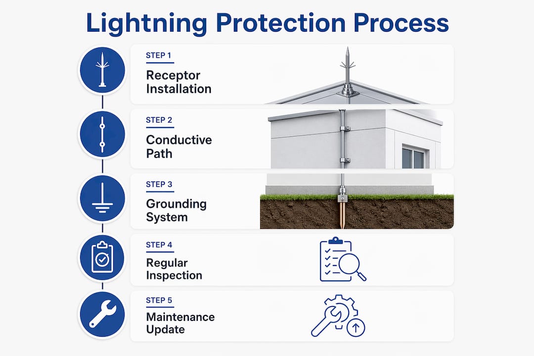
Wind turbine lightning protection, formally defined as a Lightning Protection System (LPS), is a passive electrical safety system designed to intercept lightning strikes on turbine blades and structures, then safely conduct the discharge current to ground. The LPS relies on three core components: lightning receptors, low-impedance conductive paths such as copper caps and copper mesh, and a grounding network that dissipates energy into the earth. IEC 61400-24 is the governing standard for design, inspection, and compliance. For engineers and project managers, understanding what a wind turbine lightning protection system does at a component level is the prerequisite for every design, maintenance, and upgrade decision you will make on a wind farm.
What is a wind turbine lightning protection system and how does it work?
An LPS intercepts a lightning strike before it can damage structural or electrical components. The system begins at the blade tip, where a receptor or conductive cap attracts the lightning leader and provides a preferred attachment point. From there, a low-impedance conductive path, typically copper mesh embedded in the blade laminate or a copper cap at the tip, carries the current down through the blade root, into the nacelle, and along the tower to the grounding electrode system buried in the earth.

The physics behind receptor placement have grown more precise over time. Lightning attachment modeling has evolved from electro-geometrical models to leader progression models, which better predict where a strike will attach and allow engineers to optimize receptor positions accordingly. This matters because a misplaced receptor leaves adjacent blade material exposed to side flashes and arc damage.
Grounding is where many systems fail in practice. Air gaps between blade and nacelle create high impedance points that expose main bearings to electrical discharge, accelerating bearing wear and causing faults that are expensive to diagnose. A continuous, unbroken conductive path from blade tip to earth electrode is the non-negotiable design requirement.
| LPS Component | Function | Key Material |
|---|---|---|
| Lightning receptor / tip cap | Intercepts and attracts the lightning leader | Copper (2mm press-welded plate) |
| Conductive blade path | Carries current from tip to root | Copper mesh or conductor |
| Down conductor | Routes current from nacelle to tower base | Copper or aluminum cable |
| Grounding electrode | Dissipates energy safely into earth | Copper-bonded steel rod or ring |
Pro Tip:Verify that your blade-to-nacelle connection has no measurable air gap before commissioning. A simple impedance check at this junction catches the most common cause of bearing damage before the turbine ever turns.
What are the key standards and inspection protocols for wind turbine lightning protection?
IEC 61400-24 is the definitive international standard for wind turbine LPS design and compliance. The 2024 amendment, EN IEC 61400-24:2019/A1:2024, introduces two significant additions: Lightning Measurement Systems (LMS) and Thunderstorm Warning Systems, both detailed in Annex L. These additions shift the standard from a purely prescriptive design framework toward a data-informed operational model.
The standard mandates inspections at least every 12 months and after any severe storm event. That minimum frequency is a floor, not a ceiling. High-lightning-density sites or turbines with aging blades warrant more frequent checks.
Key inspection items required under IEC 61400-24 include:
- Receptor condition: Check for erosion, corrosion, or physical displacement at blade tips and along the blade surface.
- Conductive path continuity: Measure resistance from receptor to grounding electrode. Any reading above design specification requires immediate investigation.
- Grounding system integrity: Verify electrode resistance and check for soil disturbance or corrosion at connection points.
- Surge protection devices: Inspect SPDs in the nacelle and tower base control cabinets for activation indicators.
- LMS data review: If installed, analyze strike records to identify any events where measured current exceeded the design Lightning Protection Level.
Reviewing lightning standards compliance requirements before each inspection cycle keeps your team aligned with the current version of the standard, especially given the pace of recent amendments.
Pro Tip:Log every post-storm inspection with timestamped photos of receptor condition. This documentation directly supports insurance claims and demonstrates due diligence if a damage dispute arises.
How do material choices and upgrades affect LPS effectiveness?
The shift from Glass Fiber Reinforced Polymer (GFRP) to Carbon Fiber Reinforced Polymer (CFRP) blades has fundamentally changed the lightning risk profile of modern turbines. CFRP is electrically conductive, which means lightning does not simply attach at the receptor. It can attach anywhere along the blade surface. Copper mesh overlays on CFRP blades attract the strike to the mesh rather than the carbon fiber substrate, protecting the structural laminate from thermal and mechanical damage.
Copper tip caps represent the most proven upgrade for both GFRP and CFRP blades. These 2mm press-welded copper plates form a conductive shield at the blade tip, the highest-risk attachment zone. Copper cap upgrades can reduce blade damage repair costs by up to 96% and cut the frequency of lightning-related damage events by up to 80% compared to standard OEM systems. Those figures represent a compelling return on investment for any project manager evaluating capital expenditure on protection upgrades.
The Static + Lightning Protection System (SLPS) takes continuous conductive path design further. SLPS technology uses a patented continuous contact brush design with 1 ohm impedance, tested to withstand 200kA lightning strikes per IEC standards. That impedance level is significantly lower than conventional segmented systems, which means destructive energy dissipates faster and with less stress on blade materials.
| Technology | Blade Type | Impedance | Protection Level | Key Benefit |
|---|---|---|---|---|
| Standard OEM receptor | GFRP | Variable | LPL II–III | Baseline compliance |
| Copper tip cap | GFRP / CFRP | Low | LPL I | Up to 96% cost reduction |
| Copper mesh overlay | CFRP | Low | LPL I | Prevents surface arc damage |
| SLPS brush system | GFRP / CFRP | 1 ohm | LPL I (200kA rated) | Continuous low-impedance path |
All wind turbine subcomponents should be protected to Lightning Protection Level 1 (LPL1), the highest classification under IEC 61400-24. LPL1 compliance requires conductive paths, grounding, and receptor systems tested to the most demanding parameters in the standard. Specifying anything below LPL1 for a commercial wind turbine is a risk that rarely survives a cost-benefit analysis once blade replacement costs are factored in.
What maintenance and monitoring strategies improve LPS reliability?
A maintenance program built around time-based intervals alone is no longer sufficient. Lightning Measurement Systems provide real-time and historical strike data that allow operators to shift to condition-based maintenance. When an LMS records a strike current that exceeds the turbine’s design LPL, that turbine moves to the front of the inspection queue regardless of where it falls in the annual schedule.
LMS data also carries direct financial value. Operators can use measured strike records to justify insurance premium adjustments and to prioritize repair budgets across a fleet. This is the practical meaning of the IEC 61400-24 amendment: lightning data as a financial tool, not just a compliance record.
A structured maintenance workflow for wind turbine LPS should follow this sequence:
- Pre-inspection data review: Pull LMS records and weather event logs for the period since the last inspection. Flag any strike events above design threshold.
- Visual blade inspection: Use rope access, drones, or borescope to examine receptors, tip caps, and blade surfaces for erosion, cracking, or burn marks.
- Continuity testing: Measure resistance along the full conductive path from receptor to grounding electrode. Compare against baseline values recorded at commissioning.
- Grounding system check: Test earth electrode resistance. Verify bonding connections at the tower base and nacelle are tight and corrosion-free.
- SPD inspection: Check all surge protection devices in the electrical cabinets. Replace any that show activation or degradation.
- Documentation and reporting: Record all findings with photos, measurements, and timestamps. Update the turbine’s maintenance log and flag any items requiring follow-up.
A detailed lightning protection maintenance workflow provides the procedural depth needed to standardize these steps across a multi-turbine fleet.
Pro Tip:Establish baseline resistance measurements for every conductive path at commissioning and store them in the turbine’s permanent record. Without a baseline, field measurements during annual inspections have no reference point and trending analysis becomes impossible.
Key takeaways
Effective wind turbine LPS design requires LPL1-rated components, continuous low-impedance conductive paths, and condition-based maintenance supported by Lightning Measurement System data.
| Point | Details |
|---|---|
| LPS core function | Intercepts lightning at the blade and routes current safely to a grounding electrode. |
| IEC 61400-24 compliance | Mandates annual inspections, post-storm checks, and LMS integration under the 2024 amendment. |
| Material upgrade value | Copper tip caps and mesh can cut blade damage costs by up to 96% versus standard OEM systems. |
| CFRP blade risk | Carbon fiber blades require copper mesh overlays to prevent surface arc attachment across the laminate. |
| Condition-based maintenance | LMS strike data shifts maintenance from fixed schedules to event-driven inspections, reducing downtime. |
Indelec’s perspective on where wind turbine LPS practice falls short
After decades of working with lightning protection systems across industrial and energy infrastructure, the pattern I see most often is this: operators meet the minimum standard and stop there. IEC 61400-24 compliance is the starting point, not the finish line. Turbines operating in high-keraunic zones or coastal environments face strike frequencies and current magnitudes that push against LPL1 design margins. Meeting the standard on paper while ignoring site-specific risk data is how expensive blade failures happen.
The 2024 amendment to IEC 61400-24 is the most consequential update the standard has seen in years. The formalization of Lightning Measurement Systems in Annex L gives operators a tool that most are not yet using to its full potential. Strike data should be feeding directly into fleet-level risk models, insurance negotiations, and capital planning cycles. The operators who treat LMS output as a compliance checkbox are leaving real money on the table.
On materials, the industry is still catching up to the implications of CFRP blade adoption. The electrical behavior of carbon fiber under lightning attachment is fundamentally different from GFRP, and protection systems designed for the previous generation of blades do not transfer directly. Copper mesh integration and continuous low-impedance path design are not optional upgrades for CFRP blades. They are baseline requirements.
My consistent advice to project managers: specify LPL1 across every subcomponent, install LMS on every turbine from commissioning, and treat the resulting data as an operational asset. The upfront cost is recoverable within the first avoided blade replacement.
— Indelec
How Indelec supports wind turbine lightning protection
Indelec has specialized in lightning protection since 1955, with engineering expertise that spans system design, compliance, installation, and long-term maintenance across industrial and energy infrastructure worldwide.
For wind energy projects, Indelec provides LPS application solutions covering receptor systems, conductive path design, and grounding networks built to IEC 61400-24 LPL1 requirements. The team also delivers deep earth grounding drilling services for sites where standard electrode systems cannot achieve required resistance values. Whether you are commissioning a new wind farm, upgrading aging blade protection, or building a condition-based maintenance program, Indelec’s technical team can provide site-specific assessments and compliant system designs. Contact Indelec to discuss your project requirements.
FAQ
What is a wind turbine lightning protection system?
A wind turbine lightning protection system (LPS) is a passive electrical safety system that intercepts lightning strikes at the blade and conducts the discharge current safely to a grounding electrode in the earth. It consists of lightning receptors, low-impedance conductive paths, and a grounding network designed to IEC 61400-24 standards.
How often should wind turbine LPS be inspected?
IEC 61400-24 requires inspections at least every 12 months and after any severe storm event. Sites with high lightning density or aging blades should schedule additional checks beyond this minimum interval.
Why are CFRP blades at higher lightning risk than GFRP blades?
Carbon Fiber Reinforced Polymer is electrically conductive, so lightning can attach anywhere along the blade surface rather than only at the receptor. Copper mesh overlays are required on CFRP blades to attract strikes away from the structural laminate and prevent arc damage.
What is Lightning Protection Level 1 and why does it matter?
Lightning Protection Level 1 (LPL1) is the highest protection classification under IEC 61400-24, requiring conductive paths, grounding, and receptor systems tested to the most demanding current and energy parameters. All wind turbine subcomponents should be specified to LPL1 to maximize protection against the full range of lightning strike magnitudes.
How do Lightning Measurement Systems improve maintenance decisions?
Lightning Measurement Systems record actual strike parameters in real time, allowing operators to identify when a measured current exceeds the turbine’s design LPL and trigger immediate inspection. This condition-based approach reduces unnecessary scheduled downtime while catching high-risk events that time-based intervals would miss.