Rolling Sphere Method: Radius, Calculation and Design
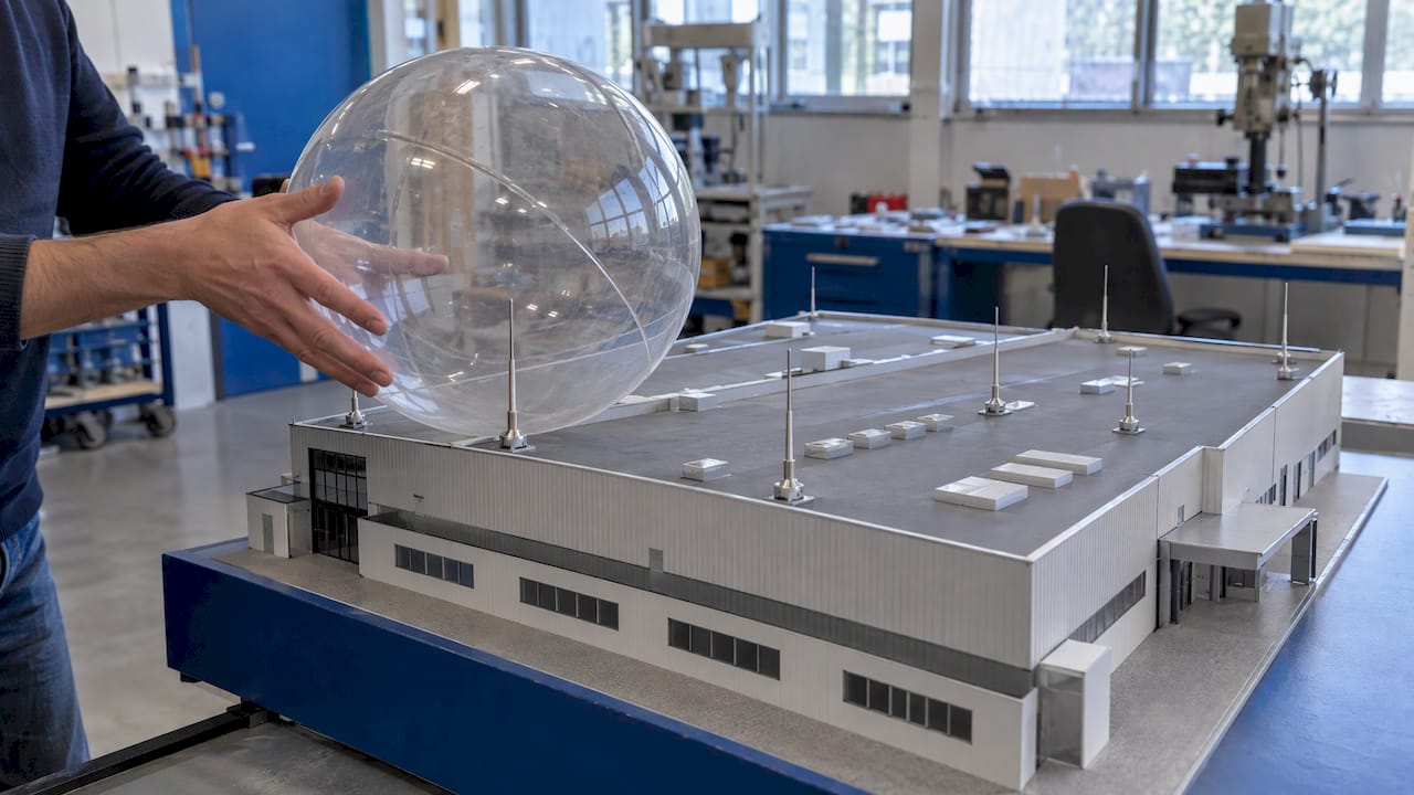
The rolling sphere method is a geometric test for finding where lightning can strike a structure. You roll an imaginary sphere over the building and its surroundings. Every point the sphere touches can take a direct strike and needs an air terminal. The sphere’s radius comes from the lightning protection level, set by the risk analysis, and runs from 20 m to 60 m. If you manage an industrial site, design a building or commission a lightning protection study, the method decides where the rods, masts and meshes go. The risk analysis that sets the radius is the step that decides the result.
TL;DR
- The method treats lightning as a sphere of fixed radius. Points it touches need air terminals. Points it cannot reach are shielded.
- Radius depends on the protection level: 20 m (Level I), 30 m (II), 45 m (III) and 60 m (IV). The level comes from the risk analysis in IEC 62305-2.
- A smaller sphere is the stricter test, because it slips between and beside protective elements more easily.
- The method is a positioning tool. It does not size conductors, earthing or surge protection, and it does not replace the risk analysis.
- On complex sites, the sphere is run on a 3D model or plan sections by an engineer, and the result is documented in the technical study.
Table of Contents
- What the rolling sphere method does
- Choosing the sphere radius
- How to carry out a rolling sphere calculation
- What the method does not do
- Standards that apply in France
- Rolling sphere versus other air-termination layouts
- From the calculation to the installed system
- Perspective
- Getting a sphere study done for your site
- FAQ
- Sources
What the rolling sphere method does
The method is a technique for determining zones of protection: a sphere is theoretically brought up to the structure and rolled over all of it. The boundary of the areas shielded from direct flashes follows from the contact points. Two uses follow from this:
- Roofs and facades: every point the sphere touches needs an air terminal, whether a rod, a conductor or a mesh.
- Masts and free-standing rods: the sphere sets the height and spacing of masts so that nearby equipment stays under their shield.
The physical idea is simple. The rolling sphere theory rests on two assumptions: the strike point is fixed when the downward leader (the channel of charge descending from the cloud) comes within striking distance of the ground or a structure, and lightning hits the nearest grounded object. The worst position for the leader tip is therefore the center of a sphere touching several grounded objects.
In France the approach is described in terms of a sphère fictive. Standards are traditionally built on a simplified electrogeometric model where the sphere radius is proportional to the intensity of the charge it represents.
Choosing the sphere radius
The radius is not a free design choice. The sphere radius of 20, 30, 45 or 60 m depends on the lightning protection level, which comes from the risk analysis in IEC 62305-2. The same source recommends 20 m for very large structures and for those holding explosive, flammable or valuable contents.
| Protection level | Sphere radius | Typical use |
|---|---|---|
| Level I | 20 m | Explosive or flammable contents, critical or very large structures |
| Level II | 30 m | High-consequence buildings |
| Level III | 45 m | Standard industrial and commercial buildings |
| Level IV | 60 m | Lower-risk structures |
The radii also appear in the French standard NF C 17-102 (September 2011), which gives 20 m, 30 m, 45 m and 60 m for Levels I to IV when it defines the protection radius of early streamer emission (ESE) air terminals.
Where the radius comes from
The radius is tied to the peak current of the strike by an empirical formula from an IEEE working group: r = 10 × I^0.65, with r in meters and I in kA. Put in the weakest current the level must intercept and you get the radius. A 3 kA strike gives about 20 m, which matches Level I. French guidance makes the same point: the method considers the weakest strike at 3 kA, evaluated at a 20 m sphere. Real strikes are far stronger, in France 100 to 300 kA, but the design must also catch the weak ones.
This explains why a smaller sphere is the stricter test. The same source notes that the danger of a small sphere lies in its greater ability to pass beside a protection. A 20 m sphere reaches into gaps that a 60 m sphere bridges, so Level I needs more air terminals, closer together.

How to carry out a rolling sphere calculation
There are two ways to work: graphically on a scaled model, or numerically with the geometry formulas. Most studies combine both.
The graphical procedure
The basic procedure is as follows:
- Scale the structure, for example 1:100, and include surrounding buildings, trees, pylons and other objects at the same scale. They can act as natural shielding.
- Set the radius from the protection level the risk analysis requires.
- Scale the sphere to the same ratio as the plan.
- Roll the sphere over the structure in every direction, around its perimeter and across the roof.
- Mark the contact points. Where the sphere touches the building, an air terminal is needed. Where it cannot reach, the area is considered protected.
A well-designed system is built so that the sphere touches only the lightning protection system and never the structure itself. A true-to-scale sphere and a model that includes neighboring buildings are both required for the result to be valid.
The geometry for a single rod
For a vertical rod of height h above the reference plane and a sphere of radius R, the protected radius at ground level follows from Pythagoras:
r₀ = √(h × (2R − h))
At a protected level of height x above that plane, the protected radius shrinks:
r(x) = √(h × (2R − h)) − √(x × (2R − x))
Worked example, Level II (R = 30 m), with a 10 m rod on a flat roof:
- At the roof plane: r₀ = √(10 × 50) = about 22.4 m.
- For a rooftop unit 5 m high: r(5) = 22.4 − √(5 × 55) = 22.4 − 16.6 = about 5.8 m.
So a 10 m rod at Level II shields a rooftop unit only within roughly 6 m horizontally. A cooling unit 12 m away is outside the shield and needs its own terminal or a closer rod. The same rod at Level IV (R = 60 m) gives r₀ = √(10 × 110) = about 33.2 m at the roof plane, which shows how much the level matters.
The formulas hold while the rod is not taller than the sphere radius. Above that height the sides of the mast can be struck, and the simple formula no longer applies.
The geometry between two conductors
For horizontal conductors the question is how far the sphere sinks between them. The penetration distance is p = r − √(r² − (d/2)²), where r is the sphere radius and d the distance between the air terminals.
Example at Level III (r = 45 m) with terminals 20 m apart: p = 45 − √(2025 − 100) = 45 − 43.9 = about 1.1 m. Any equipment, parapet or roof edge protruding more than about 1.1 m above the line between the two terminals is touched by the sphere and needs its own protection. At Level I with the same spacing (r = 20 m) the sphere sinks 2.7 m, which is why Level I spacing must be tighter.
Typical trouble spots
- Roof edges and corners: the sphere touches them first, and they are the most exposed points.
- Roof-mounted equipment: antennas, chimneys, HVAC units, solar arrays and skylights are rolled over just like the main structure.
- Stepped and sawtooth roofs: the lower roof can be shielded by the upper one, but only if the sphere cannot reach it between structures.
- Neighboring structures: a taller building beside yours can shield part of the roof. It can also be demolished, so the study should state what was assumed.
- Facades of tall buildings: on tall structures the sphere can reach the upper sides of the building, not only the roof. Where the sphere touches a facade, terminals are needed there as well.
What the method does not do
It is a positioning method. It tells you where the strike can land, not what the system should withstand. Conductor cross-sections, down-conductor spacing, earthing resistance and surge protection come from other parts of the standards. The same logic applies to the 3D tools now used on large sites: a 3D rolling sphere model is only as good as the geometry and the protection level fed into it.
There is also a ceiling on the simple version. The basic electrogeometric model is limited to mast heights up to the equivalent striking distance. For one example given there, masts taller than about 15 m fall outside what it can handle. Tall towers and structures taller than the sphere radius need the additional rules in the standards.
The method is also conservative by nature. Academic work notes it is simple and easy to apply, though calculated results do not always match observed strikes. For a facility owner that conservatism works in your favor: a design that passes the sphere test keeps its margin, and a competent designer documents the assumptions.
On high structures the air-termination design should also reduce the current in each down conductor. A meshed air-termination with a current-partition coefficient kc ≤ 0.44 cuts the current per conductor in a Level I system from 200 kA to about 88 kA. In practice the sphere places the terminals, and the interconnections then spread the current.

Standards that apply in France
Three documents matter when you commission or review a study:
- IEC 62305 (NF EN 62305): the reference series. Part 2 sets the risk analysis that defines the level. IEC 62305-3:2024 revises the positioning of air-termination conductors according to the three accepted methods, describes the positioning methods more precisely depending on structure complexity, simplifies the main text and moves detailed information to Annex D.
- Risk analysis update: IEC 62305-2:2024 introduces a single risk combining loss of human life and loss due to fire, a frequency-of-damage concept for damage that can impair internal-system availability, and ground strike-point density in place of flash density. The level, and so the sphere radius, can shift when a study is redone under the 2024 edition.
- NF C 17-102 (2011): the French standard for ESE air terminals. It uses the same four radii to relate the protection radius of an ESE terminal to its height, its efficiency and the chosen level. For buildings higher than 60 m, the requirements of section 5.2.3.4 apply for ESE terminal positioning.
For an overview of the framework, see our page on lightning standards.
Rolling sphere versus other air-termination layouts
For a large building, one rod with a radius under 20 m is no longer enough. French technical guidance describes the two oldest solutions: multiplying points on the roof perimeter with their down conductors, or meshing the outside of the building as a Faraday cage. A more recent and more economical option is a single ESE rod whose protection radius varies between 70 and 120 m depending on the level sought.
The rolling sphere method is the geometric check used for the first two approaches and for masts. The choice of layout is then a trade-off between roof access, aesthetics, the number of down conductors and the equipment on the roof. Our guide to lightning rod placement on a building goes through the practical side.
From the calculation to the installed system
A sphere calculation on paper is the start. Four things decide whether it holds up on site:
- The risk analysis is current. It fixes the level and the radius. It should be reviewed when the use of the building changes, when it is extended, or when the standard is revised.
- The model matches the as-built site. Added equipment, new neighbors and changed roof profiles all alter the contact points.
- The terminals, down conductors and earthing are designed as one system. Terminals placed correctly still fail if the down conductors or the earth are not.
- Verification is planned. The installation is inspected after commissioning and at set intervals.
Indelec’s lightning protection services cover the risk analysis (ARF) and technical study (ET), installation, and verification and maintenance. Our lightning protection services page describes each stage. Highly exposed or unusual sites show how the method is applied in practice, for instance our design example for a highly sensitive site and the sport arena design.
Perspective
The rolling sphere method is only as reliable as the inputs behind it. We see the sphere as the last step of a chain: the risk analysis fixes the level, the level fixes the radius, and the radius only means something if the model of the site is accurate.
That is why our work on a site starts with the risk analysis and the technical study, not with a rod catalog. Since 1955, and across more than 280,000 installations, our approach has been to treat the air terminals, down conductors, earthing and surge protection as one system, designed against the same protection level.
Our R&D center works on air terminals such as the Prevectron3, so that a site can be protected with the fewest, best-placed devices. For unusual sites, from airports to cable cars, the geometry rarely resembles a textbook case, and the study is where the quality of the protection is decided.
If you own or manage a facility, our advice is to ask for the sphere radius, the level and the assumptions in writing, and to have the study redone whenever the site changes.
INDELEC
Getting a sphere study done for your site
If you need a rolling sphere study, a risk analysis or a verification of an existing system, our engineers handle the whole chain, from the lightning risk analysis and technical study through installation to verification and maintenance. We supply the air terminals, lightning rods, down conductors and earthing as a single system. Start with our lightning protection services.

We serve industrial, commercial and public infrastructure sites, and projects can be run in France and internationally.
FAQ
What sphere radius should I use?
The radius follows from the protection level set by the risk analysis: 20 m for Level I, 30 m for Level II, 45 m for Level III and 60 m for Level IV. You do not choose it by preference. If the risk analysis is missing or outdated, the radius has no basis.
Can I run a rolling sphere calculation myself?
The geometry is easy to follow, and the formulas above give a quick check of a single rod or a pair of conductors. A real roof with equipment, neighbors and tall elements needs a scaled or 3D model and a documented risk analysis. For a compliant system, the study should be done and signed off by the lightning protection engineer.
Does the method apply to the sides of tall buildings?
Yes. The sphere also reaches the facades of tall structures, and where it touches them, protection is needed there as well. For buildings above 60 m, NF C 17-102 section 5.2.3.4 gives requirements for positioning ESE air terminals.
Why does a smaller sphere need more air terminals?
A 20 m sphere is smaller and sinks deeper between terminals and around edges, so it touches more points. It corresponds to weaker strikes that the system must still intercept, which is why Level I is the most demanding level.
Does the rolling sphere method replace a risk analysis?
No. It positions the air terminals, while the risk analysis under IEC 62305-2 decides whether protection is needed and at which level. The 2024 edition of that part changes how some risks are evaluated, so older analyses are worth reviewing.
Sources
- Lightning Protection Design for Substations
- Rolling sphere – method or theory?
- Chapter 5, University of Porto
- Le paratonnerre, protection normalisée contre la foudre, Cahiers Techniques du Bâtiment
- NF C 17-102, September 2011, English version
- Rolling Sphere Method for Lightning Protection Design
- The Proposition to Safety of a Lightning Protection System for High Structures, TEM Journal
- Basic of External Lightning Protection System, Part 2
- IEEE technical report on current and proposed lightning protection models
- Evaluation of Rolling Sphere Method Using Leader Potential
- IEC 62305-3:2024
- IEC 62305-2:2024 sample