A compliant U.S. industrial grounding system bonds all available electrodes into a single grounding electrode system per NEC Article 250, maintains low-impedance fault-current paths so protective devices operate, and controls touch and step potentials to protect workers. Get all three right, and you’ve covered the core of what mise à la terre industrielle demands in practice.

Quick compliance checklist — assess your site today:

  • Grounding electrode system bonds all available electrodes (rods, plates, concrete-encased, water pipe) per NEC Article 250
  • Equipment grounding conductors sized to NEC Table 250.122; grounding electrode conductors sized to NEC Table 250.66
  • Single electrode measuring above a certain resistance threshold augmented with a second electrode, installed a safe distance away
  • Soil resistivity tested before design; fall-of-potential acceptance test completed at commissioning
  • Temporary protective grounding procedures documented and followed per OSHA 29 CFR 1910.269 and 29 CFR 1926.404 before any energized work
  • Periodic retest schedule established (at minimum after major earthworks, equipment upgrades, or every few years)
  • Site survey completed, single-line grounding sketch on file, contractor qualifications verified

Immediate actions for a facility manager assessing a site today:

  • Walk the site and locate all existing electrodes and metallic underground systems
  • Commission a soil resistivity survey using the Wenner four-pin method before finalizing electrode layout
  • Sketch a single-line grounding diagram showing electrode locations, bonding conductors, and panel connections
  • Verify the installing contractor holds current qualifications and references NEC/OSHA/IEEE in their design documentation

Key Takeaways

A compliant industrial grounding system requires bonded electrodes, verified low resistance, documented test results, and a maintenance schedule — skipping any one of those four elements creates both safety risk and compliance exposure.

PointDetails
Bond all available electrodesNEC Article 250 requires every available electrode at a structure to be bonded into a single grounding electrode system.
Apply the 25 Ω augmentation ruleAny single electrode measuring above 25 Ω must be supplemented by a second electrode installed at least 6 feet away.
Test soil before you designSoil resistivity determines electrode type, depth, and spacing; design without a Wenner survey is guessing.
Document and trend resistance valuesBaseline fall-of-potential results compared over annual or multi-year intervals reliably detect degradation before it becomes unsafe.
Indelec for complex grounding workIndelec provides deep earth grounding drilling, IEEE Std 80 design, installation, testing, and certification for sites where standard rod installations are insufficient.

Table of Contents

Why robust industrial grounding protects personnel, equipment, and uptime

Grounding is not a passive safety measure. It is an active system that protects people, prevents equipment damage, stabilizes system voltages, and gives fault current a controlled path so protective devices can clear faults quickly.

Consider what happens without it. A phase-to-ground fault on an ungrounded system can leave equipment energized at dangerous voltages for extended periods. Workers contacting that equipment face lethal touch potentials. Lightning coupling into ungrounded metallic structures creates induced voltages that destroy sensitive electronics and can ignite fires. Protective relays and circuit breakers depend on fault current magnitude to operate within their trip time; a high-impedance ground path delays or prevents that trip entirely.

The operational stakes are real. Fault-induced downtime in industrial facilities typically involves not just the faulted circuit but upstream equipment, process interruptions, and post-fault inspection requirements. A well-designed grounding system reduces that exposure by ensuring faults clear fast and cleanly.

Key risks a properly designed grounding system mitigates:

  • Touch potential hazards when workers contact energized enclosures during a ground fault
  • Step potential hazards near electrode locations during high-current fault events
  • Induced voltage buildup on isolated metallic structures from nearby lightning or switching transients
  • Protective device failure to operate due to high ground-path impedance
  • EMI coupling into control and instrumentation circuits from inadequate signal reference grounding
  • Lightning backfeed through inadequately bonded metallic systems

OSHA’s grounding guidance frames this precisely: grounding creates equipotential conditions, discharges induced voltages, and ensures protective devices trip when they should. That three-part function is the engineering rationale behind every requirement in NEC Article 250.

25 Ω threshold: NEC Article 250 requires that any single grounding electrode measuring above 25 ohms of resistance to ground must be supplemented by an additional electrode. That second electrode must be installed at least 6 feet away from the first to avoid overlapping resistance zones.


What U.S. codes and IEEE practices require you to follow

The regulatory baseline for industrial grounding in the United States draws from three distinct sources: the NEC for installation requirements, OSHA for worker safety and protective grounding, and IEEE recommended practices for engineering design. Each covers different ground, and you need all three.

NEC (NFPA 70) Article 250 is the primary installation code. It governs grounding electrode systems, equipment grounding conductors, bonding, grounding electrode conductor sizing, and the 25 Ω augmentation rule. Article 250 is organized into parts covering general requirements, circuit and system grounding, grounding electrode systems, and bonding. Key sections to review during design include 250.50 (grounding electrode system), 250.52 (permitted electrodes), 250.53 (installation requirements), 250.66 (GEC sizing), and 250.122 (EGC sizing).

OSHA 29 CFR 1910.269 applies to electric power generation, transmission, and distribution work. It sets requirements for protective grounding during maintenance on energized systems, including the design of temporary grounds to withstand fault current and the sequencing of ground application. 29 CFR 1926.404 covers construction electrical safety, including grounding requirements for temporary power and fixed equipment. OSHA’s construction grounding guidance defines the two fundamental types of grounds — system/service ground and equipment ground — and emphasizes that grounding paths must be permanent and continuous.

IEEE Std 142 (the Green Book) provides recommended engineering practices for system grounding in industrial and commercial power systems. It covers solid, low-resistance, high-resistance, and resonant grounding methods, and addresses generators, transformers, and grounding impedances. IEEE Std 80 is the standard for safety in AC substation grounding, covering step and touch potential calculations and grid design. IEEE Std 1048 addresses protective grounding of power lines, including temporary grounding procedures and equipment ratings.

For grounding compliance standards, these three regulatory layers work together: NEC tells you what to install, OSHA tells you how to work safely around it, and IEEE tells you how to engineer it correctly.

Reference checklist for design and specifications:

  • NEC Article 250, Parts I–X (grounding and bonding, all installation types)
  • OSHA 29 CFR 1910.269(n) — protective grounding for power generation/transmission work
  • OSHA 29 CFR 1926.404 — grounding requirements for construction electrical systems
  • IEEE Std 142-2007 — system grounding methods and design for industrial power systems
  • IEEE Std 80-2013 — AC substation grounding, step/touch potential calculations
  • IEEE Std 1048-2016 — protective grounding of power lines, temporary grounds

What types of grounding does your industrial system actually need?

Industrial systems use several distinct grounding types, and the right choice depends on load characteristics, fault tolerance requirements, and NEC constraints.

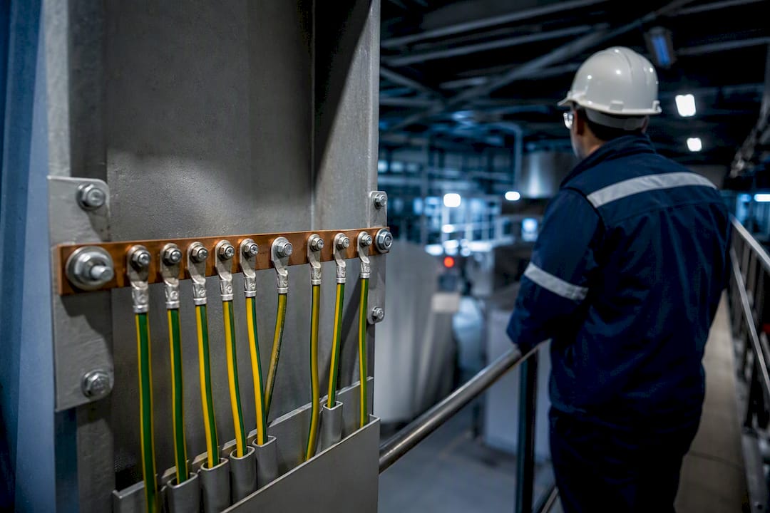
Grounding wires connected to electrical panel

OSHA’s construction grounding eTool identifies the two foundational categories: the system/service ground, which connects the neutral or a phase of the electrical supply to earth, and the equipment ground, which connects non-current-carrying metallic parts to the grounding system so fault current has a return path and protective devices operate.

Beyond those two, the grounding method for the system neutral determines fault current behavior and drives protective device coordination:

Solid grounding connects the neutral directly to ground with no impedance. It produces the highest fault current, which ensures fast protective device operation. Most distribution systems and low-voltage industrial feeders use solid grounding. The tradeoff: high fault current can damage equipment and create significant arc flash energy.

Low-resistance grounding (LRG) inserts a resistor between neutral and ground, typically limiting ground fault current to 100–400 A. This reduces arc flash energy while still allowing ground fault relays to detect and clear faults quickly. IEEE Std 142 covers LRG design in detail, including resistor sizing and relay coordination. LRG suits medium-voltage industrial systems with rotating equipment where fault energy must be controlled.

High-resistance grounding (HRG) limits fault current to a few amperes, allowing the system to continue operating during a single ground fault while an alarm alerts maintenance. NEC 250.36 permits HRG for systems up to 1,000 V where line-to-neutral loads are not connected. The critical constraint: HRG cannot be used where line-to-neutral loads exist, and it requires continuous ground fault monitoring. It suits process industries where an unplanned shutdown is more dangerous than a sustained single fault.

Ungrounded systems have no intentional neutral-to-ground connection. They can operate through a single ground fault but are prone to transient overvoltages and difficult fault location. NEC and IEEE generally discourage ungrounded systems in new industrial installations.

Isolated grounding is a technique for sensitive electronic equipment, not a system grounding method. An isolated ground (IG) receptacle runs a separate equipment grounding conductor back to the panel without connecting to the metallic raceway, reducing conducted EMI on the reference ground. NEC Article 250 permits isolated grounding for noise-sensitive equipment.

For mission-critical facilities, hybrid approaches often separate grounding strategies by load type. Motors and mechanical loads may use LRG for arc flash control, while ICT and instrumentation loads use solid grounding or isolated grounding for signal integrity. Eaton’s guidance on grounded systems in mission-critical installations addresses this hybrid approach and the NEC constraints that govern it.


How to select ground electrodes, conductors, and connectors that last

The grounding electrode system is only as reliable as its weakest physical connection. Material selection, sizing, and installation practice determine whether that system performs for decades or degrades within a few years.

Electrode types and tradeoffs:

  • Ground rods (copper-clad steel, 5/8-inch minimum diameter, 8 feet minimum length per NEC 250.52) are the most common electrode type. They suit most soil conditions but may require augmentation in high-resistivity soils.
  • Ground plates (minimum 2 sq ft of surface area for iron/steel, 0.6 sq ft for copper) work in shallow excavations where driving rods is impractical.
  • Concrete-encased electrodes (Ufer grounds) use the rebar or bare copper conductor embedded in a building’s concrete foundation. They provide excellent contact with moist soil and are highly reliable in most climates.
  • Ground rings encircle a structure with a bare copper conductor buried at least 30 inches deep. They suit substations and large industrial buildings where perimeter bonding is needed.
  • Deep vertical electrodes (driven or drilled to depths of 50–200+ feet) reach below frost line and into consistently moist soil layers. They are the preferred solution for high-resistivity surface soils.

Conductor sizing: Grounding electrode conductors (GEC) are sized per NEC Table 250.66 based on the largest service entrance conductor. Equipment grounding conductors (EGC) are sized per NEC Table 250.122 based on the overcurrent device rating. Treat these tables as minimums; upsizing is appropriate in corrosive soils, high-fault-current systems, or where conductor replacement would require excavation.

Material selection: Copper is the standard for buried grounding conductors due to its corrosion resistance. Galvanized steel is acceptable in some applications but degrades faster in acidic or high-chloride soils. Avoid aluminum for direct-buried grounding conductors — NEC prohibits it in most grounding electrode conductor applications.

Bonding: NEC Article 250 requires all available electrodes at a structure to be bonded together into a single grounding electrode system. The main bonding jumper connects the neutral to the equipment grounding system at the service. Never install parallel neutral-to-ground bonds downstream of the service — they create circulating currents and can interfere with ground fault detection.

Connection practices: Exothermic (cad-weld) connections are preferred for buried or inaccessible joints because they are permanent and corrosion-resistant. Mechanical connectors (listed compression or bolted) are acceptable where connections remain accessible and inspectable. Never use standard wire nuts or unrated connectors for grounding. Apply anti-oxidant compound on aluminum-to-copper transitions and protect exposed terminations from moisture intrusion.

Pro Tip:In soils with high sulfate or chloride content — common near coastal sites or industrial process areas — specify copper-clad or solid copper rods and exothermic connections for all buried joints. The incremental cost is small compared to excavating and replacing corroded connections five years later.


How soil resistivity testing drives your electrode and grid design

Soil resistivity is the single most influential variable in grounding electrode design. A rod driven into 500 Ω·m soil will measure far higher resistance than the same rod in 50 Ω·m soil, regardless of how well it’s installed. Test before you design.

How soil resistivity testing drives your electrode and grid design — overview diagram

Why it matters: Electrode resistance is directly proportional to soil resistivity. High-resistivity soils require deeper electrodes, multiple electrodes, chemical enhancement, or ground grids to achieve acceptable resistance values. Designing without a resistivity survey is guessing — and the consequences show up at commissioning when the fall-of-potential test fails.

Common test methods:

  1. Wenner four-pin method: Four equally spaced pins are driven in a line. Current flows between the outer pins; voltage is measured between the inner pins. Varying the pin spacing gives a resistivity profile at different effective depths. This is the standard method for pre-design surveys and substation grid design.
  2. Fall-of-potential (three-point) method: Used to measure the actual resistance of an installed electrode. A current electrode is driven at a distance from the ground rod, and a potential electrode is moved between them to find the true resistance. This is the commissioning test method, not a pre-design survey tool.

How to interpret resistivity results:

Resistivity Band (Ω·m)Soil DescriptionTypical Electrode Strategy
Below 100Moist clay, loamSingle rod often sufficient; verify with fall-of-potential
100–300Sandy loam, mixed soilsMultiple rods or ground ring; test for augmentation need
300–1,000Dry sand, gravelDeep vertical electrodes or chemical enhancement required
Above 1,000Rock, dry gravelDrilled deep electrodes, ground grids, or bentonite backfill

Design rules from resistivity data:

  1. Extend all electrodes below the frost line — frozen soil resistivity can increase by an order of magnitude, which would push a marginal system above the 25 Ω threshold in winter.
  2. Any single electrode measuring above 25 Ω requires a second electrode installed at least 6 feet away, per NEC Article 250.
  3. For substations and large industrial sites, use a ground grid sized to limit step and touch potentials under maximum fault current, with soil resistivity and fault current as the primary design inputs per IEEE Std 80.
  4. In seasonally variable soils, test during the driest season to capture worst-case conditions. Soil resistivity varies with moisture, temperature, and dissolved salts, so testing in representative conditions gives a conservative design basis.
  5. Where surface soils are highly resistive, deep vertical electrodes reaching moist subsoil layers are often more cost-effective than a large surface grid.
  6. Chemical enhancement (bentonite, conductive concrete, or ground enhancement compounds) can reduce electrode resistance in localized high-resistivity zones, but requires periodic inspection to confirm effectiveness.

Commissioning a resistivity survey:

  1. Identify the survey area and mark utility locations before driving any pins.
  2. Conduct Wenner tests at multiple orientations and locations across the site to capture spatial variability.
  3. Test during the driest season or document the season and recent precipitation for design margin purposes.
  4. Record all readings with pin spacing, orientation, and GPS coordinates.
  5. Engage a licensed engineer to interpret the resistivity profile and specify electrode type, depth, and spacing.
  6. Integrate the resistivity data into the grounding design before finalizing electrode layout or ordering materials.

How to evaluate and control touch, step, and transfer potentials

Touch and step potentials are the mechanism by which a properly functioning grounding system can still injure or kill a worker during a fault. Evaluating them is not optional for substations, switchgear rooms, or any location where fault currents are significant.

Definitions that matter:

  • Touch potential: The voltage between a worker’s hand (contacting an energized structure) and their feet during a fault. The tolerable limit depends on body weight and fault duration; IEEE Std 80 provides the calculation method.
  • Step potential: The voltage between a worker’s two feet, spaced about 1 meter apart, as fault current flows through the soil near an electrode or grid. Workers can be injured without touching any equipment.
  • Transfer potential: A hazardous voltage transferred to a remote location via a conductor (a fence, a pipe, a cable tray) connected to the grounding system during a fault.

OSHA’s protective grounding guidance requires that temporary protective grounds be designed and installed to reduce hazardous voltage differences and to permit protective devices to operate. That requirement applies during maintenance as much as during normal operation.

Mitigation techniques:

  • Ground grid geometry: Closer mesh spacing reduces surface potential gradients. IEEE Std 80 provides the equations to size mesh spacing for a given fault current and soil resistivity.
  • Equipotential mats: Portable or permanent conductive mats bonded to the grounding system create a local equipotential zone for workers. Required for substation switching and live maintenance tasks.
  • Insulating footwear and coverings: Rubber-soled boots and insulating blankets reduce the current path through the worker’s body. These are administrative controls, not substitutes for engineering controls.
  • Barricading and signage: Restrict access to high-gradient zones near electrodes during fault conditions or high-current testing.
  • Temporary protective grounding: Before any work on de-energized equipment, install temporary grounds in the correct sequence — test for absence of voltage, then apply grounds from the grounded side toward the work location. Remove in reverse order.

Pro Tip:When establishing a temporary equipotential zone for live-line adjacent work, apply the grounds before workers enter the zone and verify with a clamp meter that the temporary ground conductor is carrying no unexpected current before proceeding. An unexpected current reading means the system is not fully de-energized — stop and investigate.

Testing for step and touch potential compliance typically involves IEEE Std 80 modeling during design, followed by field verification using a fall-of-potential setup with the grid energized at a known test current. For substations, this is a design-phase calculation, not just a commissioning measurement.


Step-by-step installation sequence for industrial grounding systems

A consistent installation sequence prevents floating bonds, missed connections, and rework. Follow this order on every project.

Numbered installation steps:

  1. Pre-installation review: Obtain as-built drawings, locate all underground utilities (call 811), and confirm electrode locations don’t conflict with buried services or future excavations.
  2. Site layout: Mark electrode positions, conductor routes, and bonding connection points. Confirm spacing meets NEC requirements (minimum 6 feet between augmentation electrodes).
  3. Excavation and trench preparation: Excavate conductor trenches to the required depth (minimum 24 inches for direct-buried conductors per NEC 250.53, or per local AHJ). Prepare electrode driving locations.
  4. Electrode installation: Drive ground rods using a mechanical driver or pneumatic hammer. For rock or high-resistivity soils, drill and install deep vertical electrodes. Inspect each rod for straightness and full penetration.
  5. Conductor routing and fastening: Pull grounding conductors through conduit or lay in trench. Avoid sharp bends that could damage conductor insulation or reduce cross-section. Secure at required intervals.
  6. Connections and bonding: Make all exothermic welds before backfilling. For accessible connections, use listed compression connectors torqued to manufacturer specifications. Record torque values.
  7. Corrosion protection: Apply anti-oxidant compound at all accessible terminations. Wrap buried mechanical connections with corrosion-resistant tape or mastic. Mark all buried electrode locations on the as-built drawing.
  8. Backfill and compaction: Backfill trenches in lifts, compacting to avoid settlement that could stress conductors. Use native soil unless chemical enhancement is specified.
  9. Inspection before testing: Walk the installation against the as-built sketch. Confirm all electrodes are bonded, all conductors are connected, and no temporary bonds remain in place.
  10. Testing: Conduct fall-of-potential tests on each electrode or electrode group. Document results. Verify continuity of all equipment grounding conductors with a low-resistance ohmmeter.

Field QA checklist items to capture during installation:

  • As-built sketch updated with actual electrode locations and depths
  • Torque or weld records for every connection
  • Corrosion protection applied and documented
  • Electrode depth confirmed (measured, not assumed)
  • All temporary construction grounds removed before energization
  • Test results recorded with date, method, instrument, and technician name

CPWR’s electrical task analysis for grounding flags ergonomic risks that are easy to overlook: handling 10-foot ground rods, bending heavy copper conductors, and working in confined trenches. Plan for wire benders, reels, and mechanical rod drivers before the crew arrives on site. Injuries during grounding installation are preventable with the right tooling and task sequencing.


Field testing methods, acceptance criteria, and a maintenance schedule

Testing is where design intent meets physical reality. A grounding system that looks correct on paper can fail commissioning due to poor connections, wrong soil assumptions, or missed electrodes.

Test methods and what each proves:

Test MethodPurposeKey LimitationWhen to Use
Fall-of-potential (3-point)Measures true electrode resistance to remote earthRequires disconnecting electrode from system; nearby metallic structures can skew resultsCommissioning; periodic retest of individual electrodes
Clamp-on earth testerMeasures resistance of electrode in a multi-electrode system without disconnectingRequires a complete current loop; not valid for single isolated electrodesLarge sites with bonded electrode systems; quick periodic checks
Low-resistance continuity (milliohm meter)Verifies bonding conductor integrity and connection resistanceDoes not measure electrode-to-earth resistanceVerifying EGC continuity and bonding jumper connections
Step/touch potential field measurementConfirms surface gradient compliance under test currentRequires specialized equipment and engineering interpretationSubstations; high-fault-current locations; post-fault assessment

Acceptance criteria:

NEC Article 250 does not mandate a single numeric resistance target for all electrodes — the 25 Ω threshold triggers augmentation for single rods, not a pass/fail for the overall system. IEEE Std 142 and IEEE Std 80 provide design-goal guidance: for critical industrial systems and substations, a design target of approximately 5 Ω or less is commonly referenced in engineering practice, though the actual acceptable value depends on fault current magnitude, protective device settings, and step/touch potential calculations. The TDEC transmission line grounding guide reinforces that soil resistivity and fault current are the primary drivers of grid sizing, not a single universal resistance number.

Recommended maintenance schedule:

  • Commissioning: Full fall-of-potential test on all electrodes; continuity verification on all EGCs and bonding conductors; document baseline resistance values.
  • Annual: Visual inspection of all accessible connections, terminations, and conductor routing; clamp-on resistance check on bonded electrode systems.
  • Every 3–5 years: Full fall-of-potential retest; compare to baseline to identify trends; inspect buried connections where accessible.
  • After trigger events: Retest after major earthworks, new construction near electrodes, significant equipment upgrades, or any ground fault event that may have damaged conductors.

Trending resistance values over time is the most reliable way to detect degradation before it becomes a safety issue. A connection that reads 0.5 Ω at commissioning and 4 Ω three years later is telling you something — find it before a fault does.

Pro Tip:Keep a grounding test log in a format that allows year-over-year comparison by electrode location. A spreadsheet with date, instrument, technician, weather conditions, and measured resistance per electrode takes 10 minutes to update and can prevent a serious incident.

For detailed maintenance procedures, Indelec’s practical grounding maintenance guide covers inspection intervals and recordkeeping practices aligned with IEEE recommendations.


Special considerations for substations, generators, UPS, and EV charging

Three installation types consistently generate grounding questions that standard NEC Article 250 guidance doesn’t fully resolve. Each has specific design and procedural requirements.

Substations

Substation grounding design is governed primarily by IEEE Std 80. The goal is not just low resistance — it’s controlling step and touch potentials under maximum fault current. A substation with 10 kA available fault current and 0.5-second clearing time requires a grid designed to keep surface gradients within tolerable limits for a 50 kg or 70 kg person, per IEEE Std 80 body weight assumptions.

Key design requirements:

  • Ground grid sized to dissipate fault energy without conductor damage (check minimum conductor size per IEEE Std 80 thermal equations)
  • Mesh spacing calculated to limit touch potential at worst-case grid corners
  • Equipment grounds and fence grounds bonded to the grid; fence grounding requires careful attention to transfer potential if the fence extends beyond the grid perimeter
  • Soil resistivity and two-layer soil model used as design inputs, not a single average value

Generators and UPS systems

Generator neutral grounding is one of the most frequently misapplied areas of NEC Article 250. The key rule: a separately derived system (a generator with a switched neutral) requires its own grounding electrode and system bonding jumper at the generator. A generator that transfers the neutral through the transfer switch is not a separately derived system and does not get a separate bond.

IEEE Std 142 addresses generator grounding in detail, including HRG constraints with UPS loads. HRG works well for motors but creates problems when line-to-neutral loads (standard in most UPS systems) are present — NEC 250.36 prohibits HRG where line-to-neutral loads are connected. Verify the load mix before specifying HRG for a generator-backed system.

EV fast-charging installations

EV charging infrastructure introduces grounding challenges that many facility teams haven’t encountered before. Multiple high-power chargers on a single site create multiple grounding electrode connections, which must all be bonded into the site’s grounding electrode system. Separating signal/communication grounds from power grounds is critical for charger reliability — conducted noise on the power ground can corrupt CAN bus and communication signals.

Lightning and transient protection is particularly important for outdoor charging installations. Surge protective devices (SPDs) at the service entrance and at each charger panel, coordinated with the site grounding system, reduce transient damage risk. Indelec’s EV charging infrastructure services address grounding and surge protection as part of a complete charging installation audit.

Risk checklist for special installations:

  • Substations: IEEE Std 80 step/touch potential calculations completed and documented
  • Generators: separately derived system status confirmed; bonding jumper location correct
  • UPS systems: HRG compatibility with line-to-neutral loads verified before specification
  • EV charging: all charger grounds bonded to site electrode system; SPDs installed and coordinated; communication grounds separated from power grounds

What experienced installers know that the code doesn’t say

Code text tells you what to do. It rarely tells you what goes wrong in the field and why. These are the failure modes that show up repeatedly in industrial grounding work.

Common field failure modes:

  • Corroded exothermic welds in coastal or industrial soils: Even cad-weld connections can corrode in high-sulfate or high-chloride environments. Specify copper-clad rods and inspect accessible welds during every maintenance cycle.
  • Undocumented parallel neutrals: Older industrial facilities often have multiple neutral-to-ground bonds installed by different contractors over decades. These create circulating currents, interfere with ground fault detection, and make resistance measurements unreliable. Audit the neutral-to-ground bonding topology before testing.
  • Buried metallic services skewing fall-of-potential results: A buried water main or gas line running parallel to the test electrode layout will conduct current and produce a falsely low resistance reading. Always check utility maps and adjust test electrode orientation to avoid parallel metallic paths.
  • Rods driven at an angle: A rod driven more than 45 degrees from vertical has significantly more resistance than a vertical rod of the same length. Use a mechanical driver with a guide to keep rods straight.
  • Missing bonding on added equipment: Every new metallic enclosure, cable tray, or equipment frame added after initial installation must be bonded to the grounding system. Incremental additions over years can leave significant metallic masses floating.

Ergonomic planning: CPWR’s grounding task analysis documents the physical demands of grounding installation — handling 10-foot rods, bending heavy copper conductors, working in trenches. Provide wire benders, conductor reels, mechanical rod drivers, and lifting aids. Plan crew handoffs for heavy lifts. These aren’t optional comforts; they prevent injuries that delay projects and create liability.

Pro Tip:Test ground resistance in both wet and dry seasons before finalizing a design. Soil resistivity varies significantly with moisture content, and a system that passes in spring may exceed the 25 Ω threshold in August. Seasonal testing data gives you the margin to design for worst-case conditions.

For a broader view of how grounding technology is evolving, Indelec’s 2026 engineer’s guide to grounding technology advances covers monitoring systems and new electrode materials worth evaluating for new installations.


Indelec’s perspective on what actually matters in industrial grounding

The debate between deep electrodes and chemical enhancement comes up on almost every difficult site. Chemical enhancement (bentonite, conductive concrete) is faster and cheaper upfront, but it requires periodic inspection and can lose effectiveness as the compound migrates or dries out. Deep vertical electrodes reach stable, moist soil layers that don’t change seasonally. For mission-critical facilities or sites where excavation for maintenance is expensive, deep electrodes are the more defensible long-term choice.

The HRG versus solid grounding decision is more nuanced than most specifications acknowledge. HRG gives you fault-ride-through capability and time to locate a fault without a process shutdown. But it requires continuous ground fault monitoring, trained operators who know what to do when the alarm sounds, and a load mix that excludes line-to-neutral connections. Facilities that specify HRG without those three elements in place end up with a system that alarms and gets ignored — which is worse than solid grounding.

Documentation is the part of grounding work that gets cut when schedules compress. That’s the wrong tradeoff. A grounding system without baseline test records is a system you can’t trend, can’t troubleshoot efficiently, and can’t demonstrate compliance on during an OSHA inspection. The hour spent documenting commissioning results is worth more than almost any other hour on the project.

When a site’s soil conditions, fault current levels, or installation complexity exceed what an in-house team can reliably design and verify, engaging a specialist with IEEE Std 80 modeling capability and deep-earth installation experience is the right call.


Indelec’s grounding and lightning protection services for complex industrial sites

Sites with poor soils, high fault currents, or mission-critical uptime requirements need more than a standard rod-and-conductor installation. Indelec’s deep earth grounding drilling services address exactly those conditions: vertical electrode installation to depths that reach stable, low-resistivity soil layers, combined with soil resistivity testing, system design, installation, and certification.

Indelec

Indelec’s scope covers the full grounding and lightning protection system lifecycle: risk assessment, electrode system design, installation, fall-of-potential testing, and periodic certification. For facilities where grounding and lightning protection interact — substations, outdoor process areas, EV charging farms — Indelec engineers both systems together, which eliminates the coordination gaps that create liability when they’re designed separately.

Situations where engaging Indelec makes sense:

  • Large substations requiring IEEE Std 80 step/touch potential modeling and grid design
  • Sites with surface soil resistivity above 300 Ω·m where standard rods won’t achieve acceptable resistance
  • Mission-critical facilities (data centers, hospitals, process plants) where grounding failure has direct operational consequences
  • EV charging farms requiring coordinated grounding, bonding, and surge protection across multiple charger installations
  • Facilities with no baseline grounding test records that need a compliance audit before an OSHA inspection

Contact Indelec through the services overview page to discuss your site’s grounding requirements and get a qualified assessment.


Authoritative references and primary sources to consult

  • NEC (NFPA 70) Article 250: The primary U.S. installation code for grounding and bonding. Consult during design for electrode system requirements, conductor sizing, and bonding rules.
  • OSHA 29 CFR 1910.269 and 29 CFR 1926.404: OSHA’s worker safety requirements for protective grounding and construction electrical systems. Consult before any energized or de-energized maintenance work.
  • IEEE Std 142 (Green Book): Recommended practices for system grounding in industrial power systems. Consult when selecting grounding method (solid, LRG, HRG) and designing generator or transformer grounding.
  • IEEE Std 80: Safety in AC substation grounding. Consult for step/touch potential calculations, grid sizing, and substation design.
  • IEEE Std 1048: Protective grounding of power lines. Consult for temporary grounding procedures, equipment ratings, and sequencing during maintenance.
  • TDEC Transmission Line Grounding Guide: Practical guidance on grid design, soil resistivity, and step/touch potential controls for transmission and substation applications.
  • CPWR Electrical Task Analysis: Grounding: Field safety and ergonomic guidance for grounding installation crews. Consult during project planning for tooling and task sequencing.
  • Indelec grounding standards overview: Practical summary of NEC, OSHA, and IEEE requirements for facility managers and engineers reviewing compliance status.

Sources